Lower Roller Names
Track Roller, Bottom Roller, Lower Roller
These terms commonly refer to the lower rollers that support and guide the load-carrying section of the track chain. A buyer should still confirm the actual machine and roller position.
Lower Undercarriage Support
FY Machinery brings together undercarriage manufacturing and international supply. Compare selected roller specifications, confirm the mounting dimensions and send your machine references for product matching and quotation.
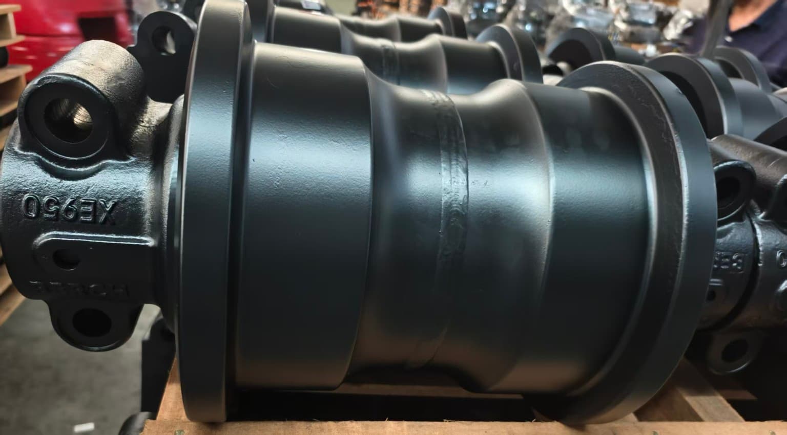
Product & Terminology Guide
A track roller supports the machine through the lower section of the undercarriage and helps guide the track chain along its loaded path. Correct terminology helps keep lower rollers distinct from the return-support rollers above the track frame.
Lower Roller Names
These terms commonly refer to the lower rollers that support and guide the load-carrying section of the track chain. A buyer should still confirm the actual machine and roller position.
Upper Roller Names
These terms refer to rollers that support the returning upper section of the track chain where used. Their position and role differ from a lower track roller.
Do Not Confuse Them
Track rollers support the lower, loaded chain path; carrier rollers support the upper return path. They are not interchangeable names for the same undercarriage position.
View Carrier RollersMachine Applications
Excavator track roller and dozer track roller requirements can look similar at a glance, but replacement track rollers must be reviewed against the specific machine and undercarriage arrangement.
Excavator Application
Identify an excavator track roller by machine model, part number when available, the rectangular four-hole mounting pattern, center distances in both directions and bolt hole diameter. Single / double flange is not the primary selection method for our excavator rollers.
View Excavator Undercarriage PartsBulldozer Application
Bulldozer track rollers require Single Flange / Double Flange identification. One bulldozer can use both types. Confirm the flange configuration together with the machine model, part number and mounting dimensions.
View Bulldozer Undercarriage PartsIdentification & Dimensions
For an excavator, confirm the model and part number, then measure the rectangular four-hole mounting pattern in both directions and the hole diameter. Provide a drawing for special requirements.
1 / Between mounting blocks. Measure from one hole center to the corresponding hole center on the other block.
2 / Within each mounting block. Measure the other direction center to center, rather than across a diagonal.
3 / Bolt hole diameter. Record it separately and send a marked photo. These numbered measurement points are separate from the Type I–V letter references.
Identify Single Flange or Double Flange before confirming a bulldozer roller. One machine can use both types.
FY identification schematics · Not to scale. Actual profiles and mounting dimensions require confirmation.
Use the corresponding type to read A–L in the selected specifications below. These are reference schematics, rather than manufacturing drawings. Dimensions are in millimetres; M-prefixed values are thread designations.
A / B: diameter references. C–G: axial references. H / I: end-view references. J / K / L: mounting-block references for Types IV and V. A dash means the source does not specify that field. Type III has no D value; Types I–III have no J–L values.
Representative Specifications
Nine selected representative specifications are shown for reference. Additional dimensions and model-specific variants are available. Model references help identify a configuration; final selection must be confirmed by machine model, part number, drawing or mounting dimensions.
Weight in kg · Dimensions in mm · M12 / M14 / M18 are thread designations, not bolt hole diameters · — = not specified in the reference table.
Selected Model References: SY16
Confirm final selection using the model, part number, drawing or mounting dimensions.
Selected Model References: SY35
Confirm final selection using the model, part number, drawing or mounting dimensions.
Selected Model References: SY55–SY65
Confirm final selection using the model, part number, drawing or mounting dimensions.
Selected Model References: SY75
Confirm final selection using the model, part number, drawing or mounting dimensions.
Selected Model References: SY95–SY155
Confirm final selection using the model, part number, drawing or mounting dimensions.
Selected Model References: SY185–SY265 / Rotary drilling SR150 / PC200-5,6
Confirm final selection using the model, part number, drawing or mounting dimensions.
Selected Model References: SY285–SY365 / Rotary drilling SR180, SR200
Confirm final selection using the model, part number, drawing or mounting dimensions.
Selected Model References: SY465 / PC400-3,5
Confirm final selection using the model, part number, drawing or mounting dimensions.
Selected Model References: SY700, SY850
Confirm final selection using the model, part number, drawing or mounting dimensions.
Product Media
Machine Application
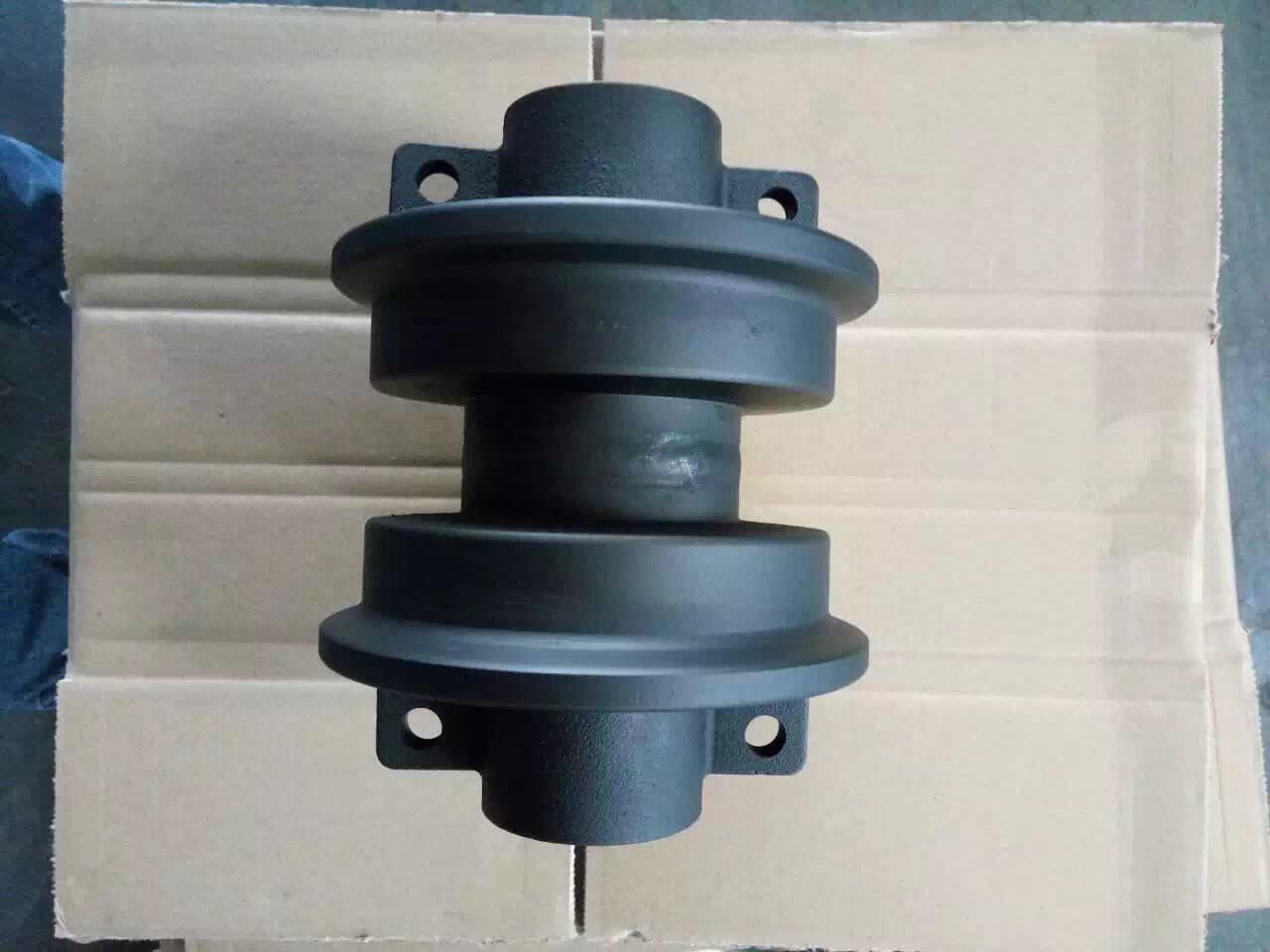
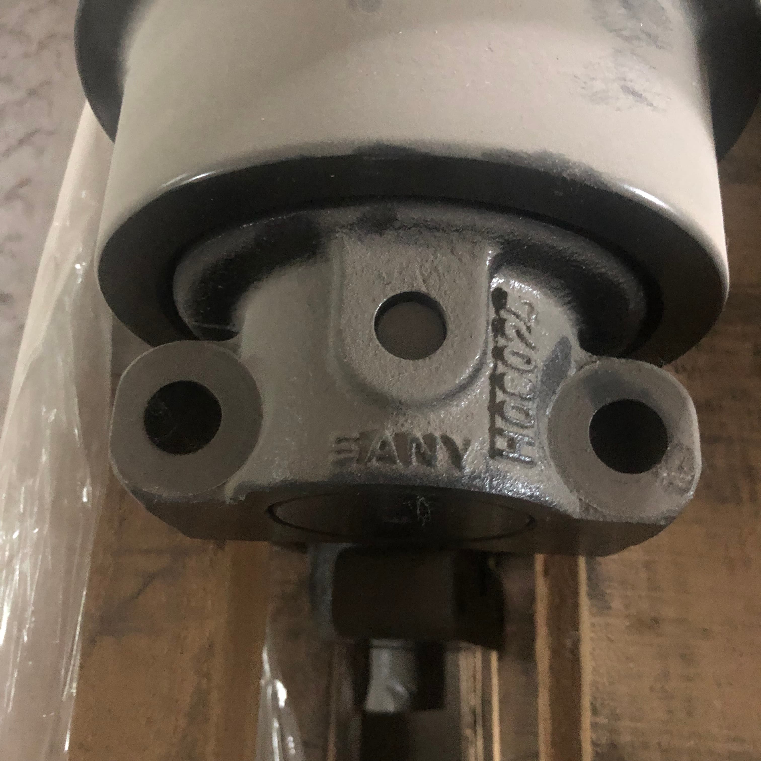
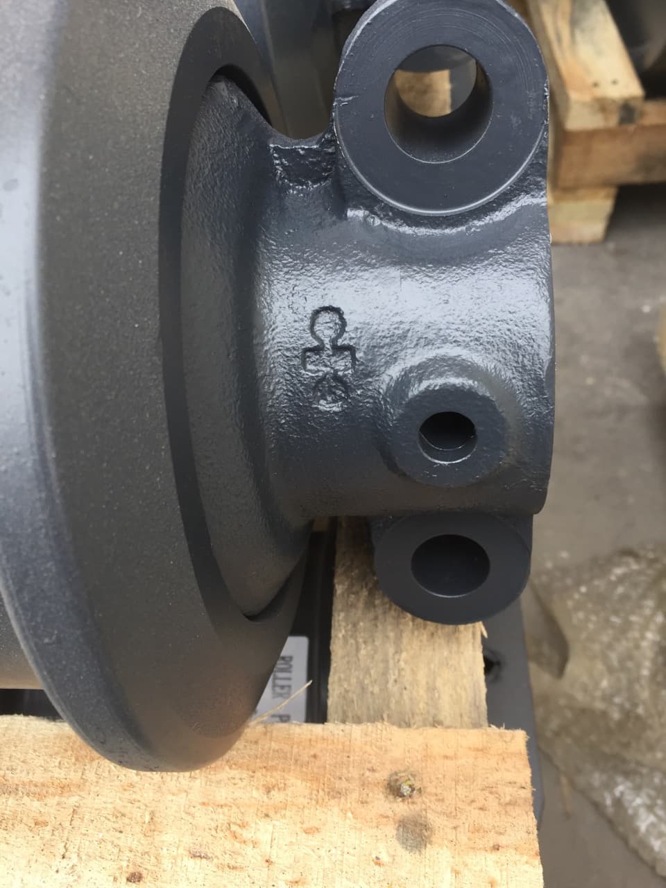
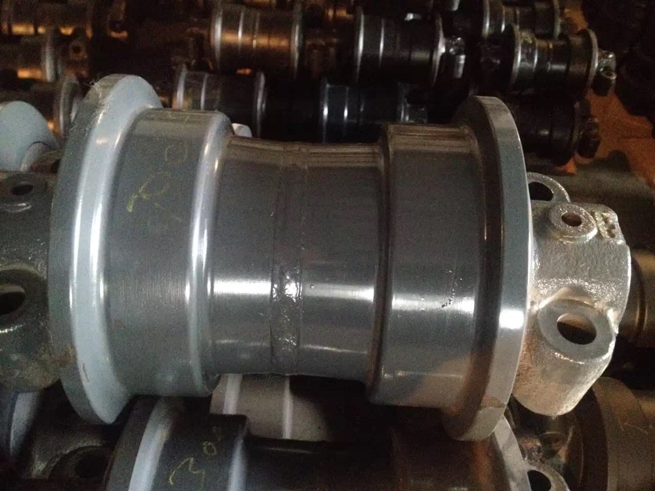
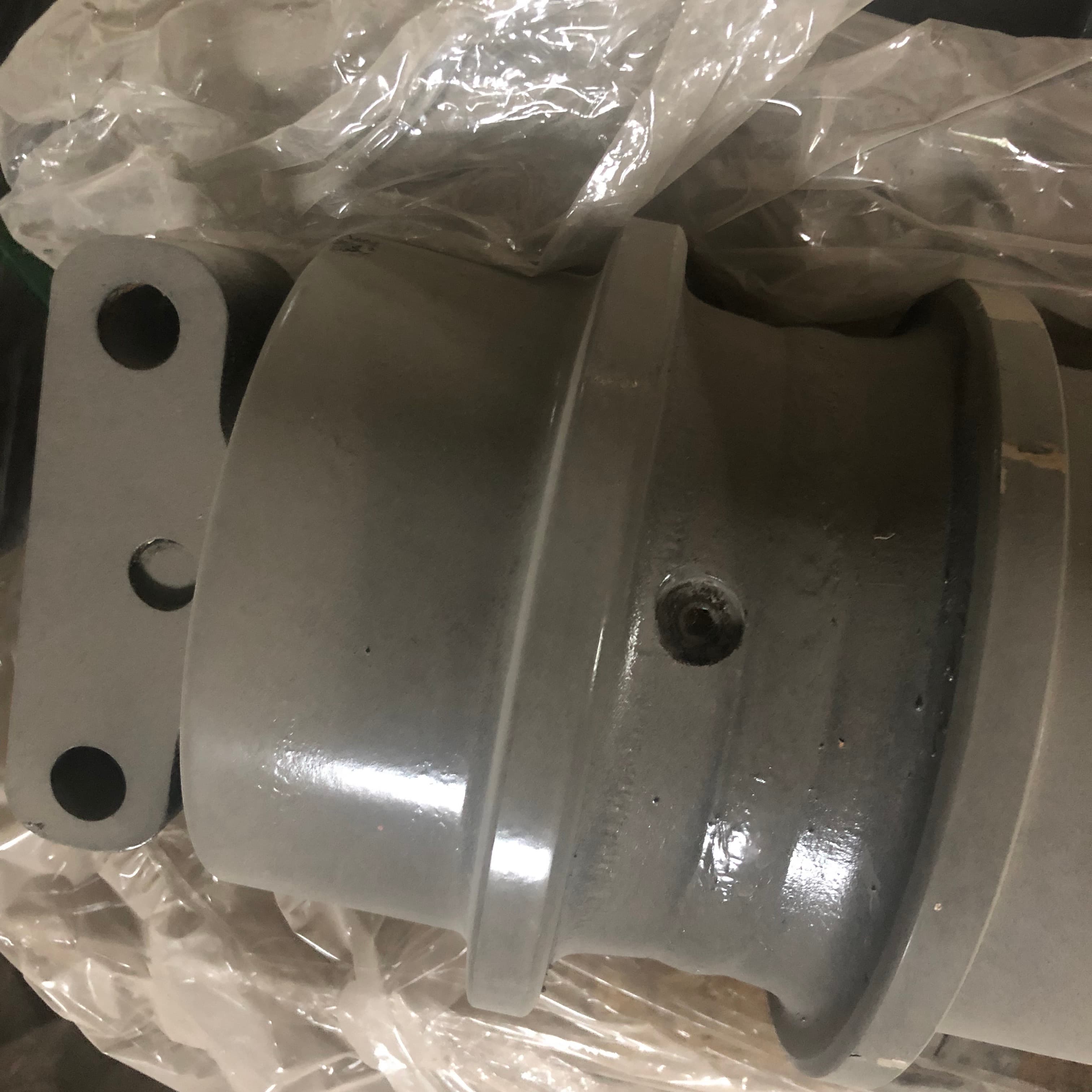
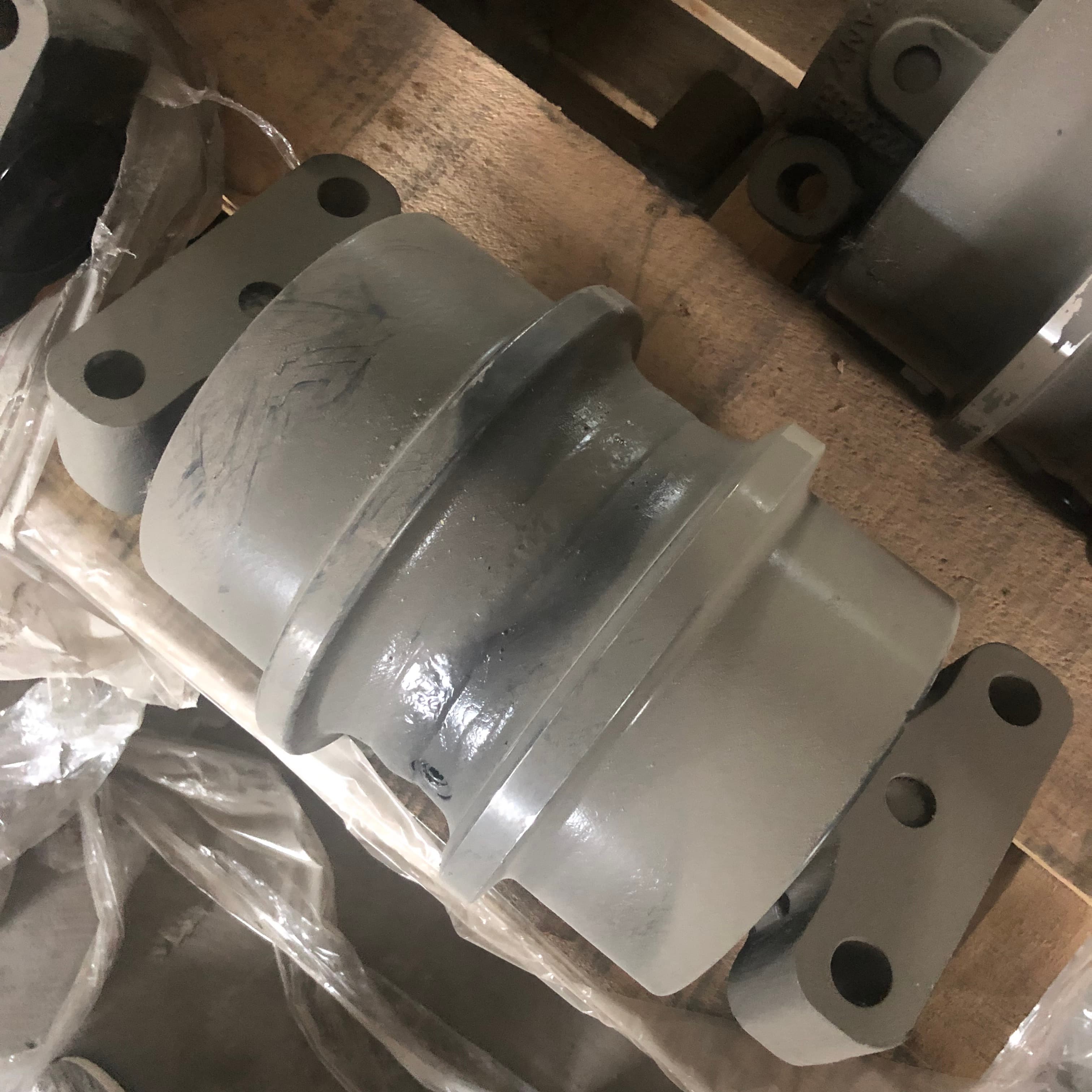
Machine Application
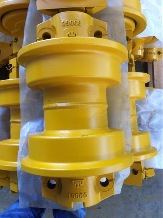
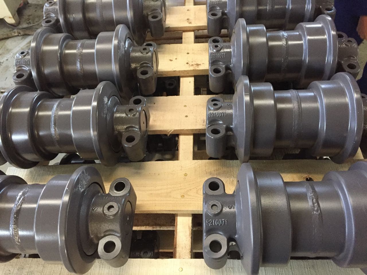
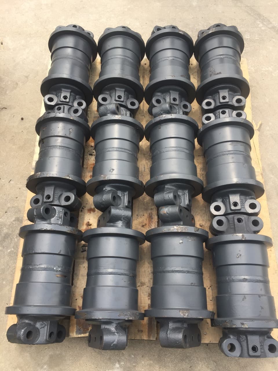
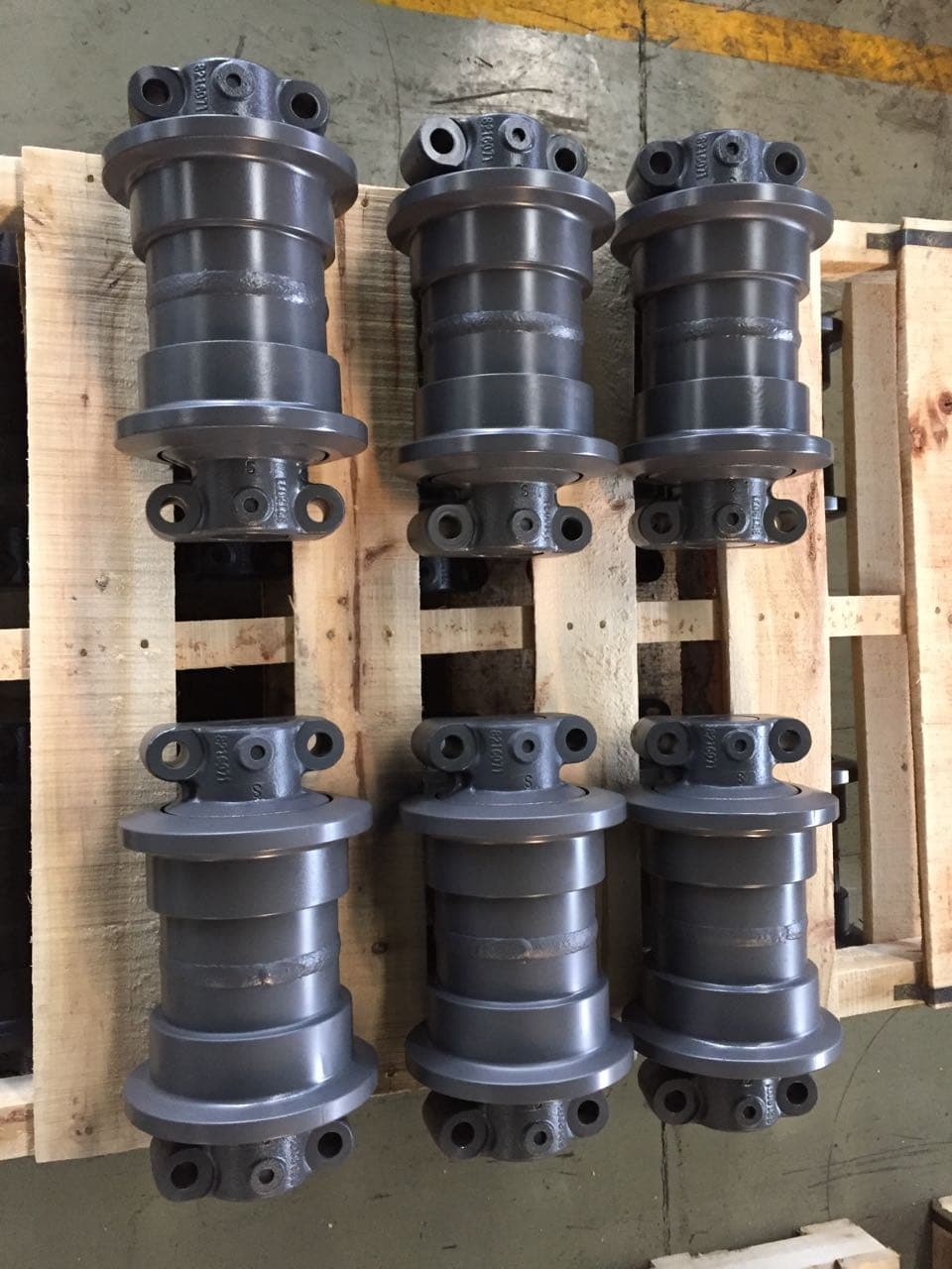
Bulldozer Configuration
A Single Flange roller has one raised flange on each side; a Double Flange roller has two on each side. One bulldozer can use both configurations. Identify the required type and confirm the machine model, part number and mounting dimensions.
For excavator track rollers, begin with model, part number and the rectangular mounting-hole pattern. The Type I–V references above describe the supplied dimension table; they are not a bulldozer flange classification or a fitment guarantee.
Inspection Clues
The following observations can justify closer inspection of the roller and related undercarriage. They are not universal wear or replacement limits.
Follow the machine-specific service guidance and use qualified technical judgment for inspection and replacement decisions.
Replacement-Part Matching
Similar-looking lower rollers can differ by machine and undercarriage configuration. Send confirmed references instead of relying on appearance or terminology alone.
Track roller vs carrier roller guideStart with the make and complete model designation from the machine plate or records.
Share the number from the roller, parts book, label, drawing or previous purchase record.
Measure center to center in both directions: between the two mounting blocks and between the two holes on each block. Send both distances in millimetres; do not substitute a diagonal.
Measure the mounting-hole diameter separately. Send a marked photo so the measurement points are clear. Thread designations in the specification table are not mounting-hole diameters.
Provide a drawing for special configurations or stricter dimensional requirements. Final selection is reviewed against the specific model, part reference and mounting dimensions.
Manufacturing / Sealing / Inspection
Most FY track roller bodies use 40Mn2 steel and are produced primarily by forging. The roller body is quenched, with a typical hardness range of HRC45–52 for the applicable specifications. Material and treatment requirements are confirmed for the specific roller.
Floating seals and sealing rings are used for sealing. Each roller is filled with oil for internal lubrication before final inspection. Special sealing or lubrication requirements should be stated with the inquiry.
Every finished track roller undergoes air-tightness, oil-leak and rotation checks. These checks are part of final inspection; they do not replace confirmation of the required model and mounting configuration.
Dimensions are checked by sampling. Dedicated moulds and tooling for each specification help maintain dimensional consistency. Send a drawing when your order has special dimensional or inspection requirements.
B2B Supply Support
For buyers comparing track roller suppliers, FY Machinery provides manufacturing-backed supply through an affiliated operation under common control. We review confirmed requirements for product matching and direct quotation, then coordinate production and order follow-up.
FY Machinery coordinates directly with the affiliated manufacturing operation on confirmed product and order requirements.
Machine model, part number, photos, both mounting-hole center distances, hole diameter, drawing and quantity are reviewed together before confirmation.
Applicable identification, quantity, visual, dimensional, packing, and order-reference checks can be coordinated for the confirmed scope.
Production-site visits can be coordinated where appropriate to the product, order stage, and agreed arrangement.
Buyer Questions
A track roller is a lower undercarriage roller that supports the machine through the track system and guides the load-carrying section of the track chain along the track frame. It is also commonly called a bottom roller or lower roller.
A track roller sits in the lower undercarriage and supports the loaded lower track-chain path. A carrier roller, also called a top roller or upper roller, supports the returning upper section of the chain. They have different positions and roles and should not be treated as interchangeable parts.
Leakage, visible damage, abnormal rotation or noise, uneven wear, and track-guidance problems are reasons to inspect the roller and related undercarriage more closely. These observations are not universal replacement limits; use the machine-specific service guidance and qualified technical judgment.
Start with the machine model and part number if available. For an excavator roller, provide both center distances of the rectangular four-hole mounting pattern and the bolt hole diameter. Include clear photos, quantity and a drawing for special requirements. For a bulldozer, also identify Single Flange or Double Flange. Final matching requires review of the supplied references.
Request for Quotation
Include the machine model, part number if available, clear photos and quantity. Send both center distances of the mounting pattern and the bolt hole diameter in millimetres, plus a drawing for special requirements. For bulldozer rollers, specify Single Flange or Double Flange. FY will review your references for product matching and quotation.