FY MachineryUndercarriage Parts

Upper Undercarriage Support

Carrier Rollers for Excavators & Bulldozers

FY Machinery brings together undercarriage manufacturing and international supply. Compare carrier roller structures and published dimensions, then send your machine model, part number and matching references for confirmation and quotation.

Excavator carrier roller product view
Product GroupTrack System

Carrier Rollers

Carrier RollerTop RollerUpper Roller

Machine Applications

Carrier roller applications and related track parts

A carrier roller supports and helps guide the upper or return run of the track chain within an applicable undercarriage. Excavator and bulldozer requirements vary by machine and track arrangement, so replacement matching must use the actual application details.

Excavator Application

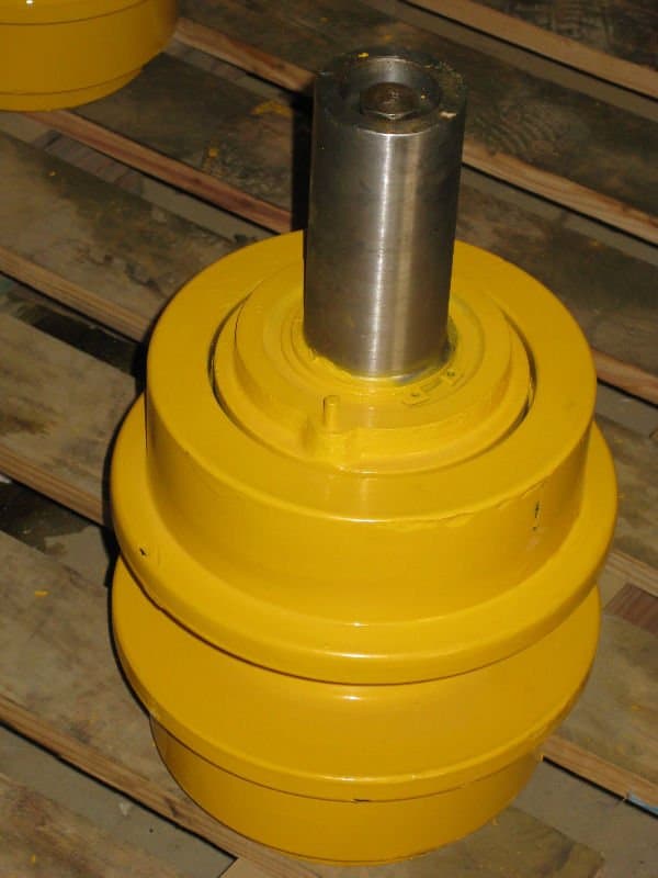
Excavator Carrier Roller

In an applicable excavator undercarriage, the carrier roller supports and guides the returning upper section of the track chain. The required replacement depends on the machine and its actual upper roller arrangement.

View Excavator Undercarriage Parts
Bulldozer Application

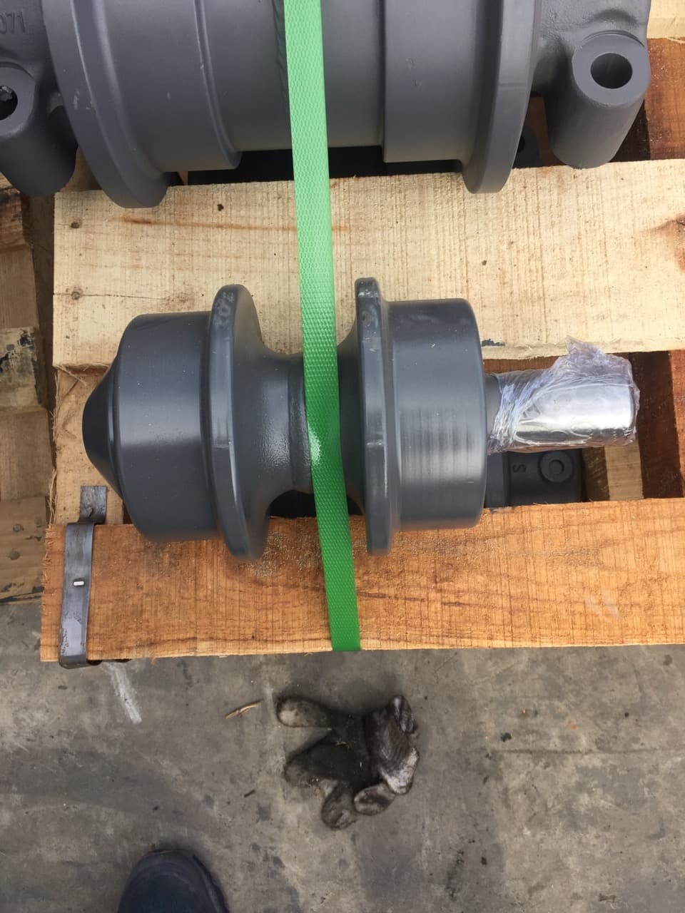
Bulldozer Carrier Rollers

In an applicable bulldozer undercarriage, carrier rollers provide upper support and guidance for the return run of the track chain. Matching still depends on the specific machine and track-frame arrangement.

View Bulldozer Undercarriage Parts

Lower Roller Context

Track Rollers

Track rollers, also called bottom rollers in some buyer terminology, support and guide the lower loaded run of the track chain. Their position and role differ from carrier rollers above.

Compare Track Rollers

Related Track Component

Track Chains

The carrier roller interacts with the returning upper section of the track chain. Clear chain-path context can help explain the application during replacement identification.

View Track Chains

Related Guidance Component

Idlers

Idlers guide the track chain through another part of its path. Reviewing nearby undercarriage components can provide useful context for a coordinated parts inquiry.

View Idlers

Related Drive Component

Sprockets & Segments

Sprockets and segments engage the track chain at the drive end of the undercarriage and may be relevant when the requested scope covers more than the upper rollers.

View Sprockets & Segments

Product Media

Carrier Roller Product Images

Machine Application

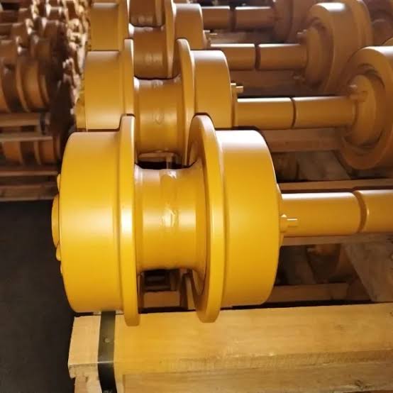
Excavator Carrier Rollers

Product Gallery

Excavator carrier roller structure view

Product Details

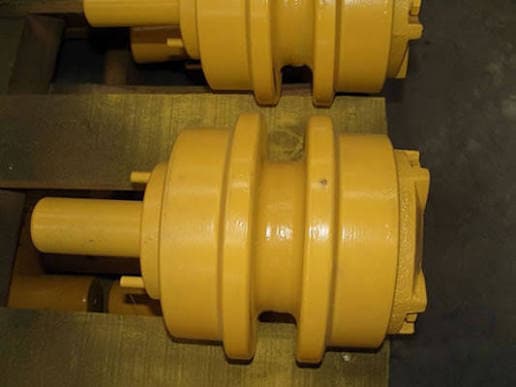
Excavator carrier roller detail view

Machine Application

Bulldozer Carrier Rollers

Product Gallery

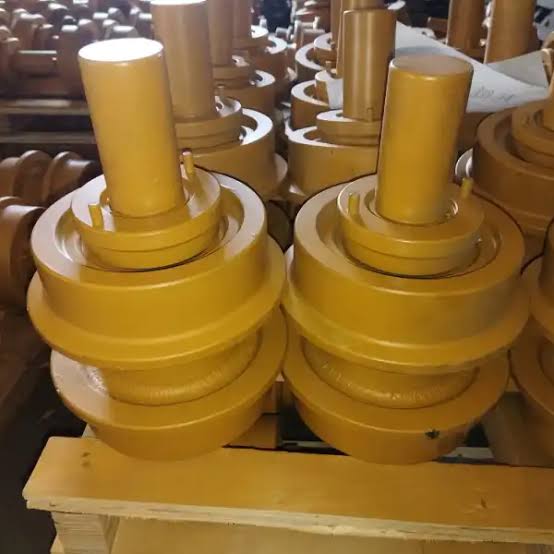
Bulldozer carrier rollers arranged in rows
Bulldozer carrier roller product view
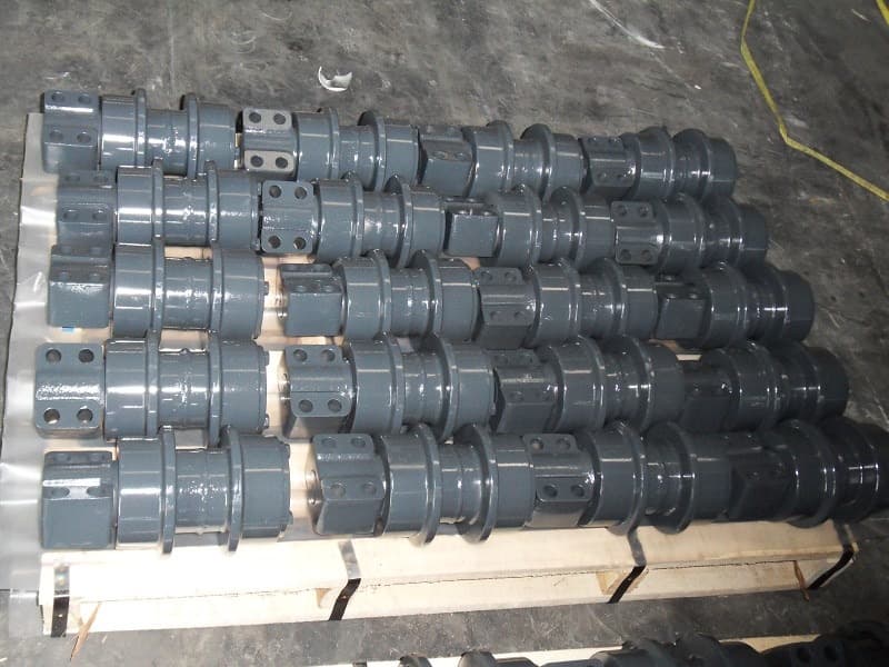
Bulldozer carrier roller angle view

Structure & Identification

Match the structure before measuring

Most standard excavator and bulldozer carrier rollers have a similar shaft-style appearance. A small number of special excavator configurations use different mounting arrangements, so the measurement path depends on the actual structure.

Standard shaft-style carrier roller

Model → Part Number → Shaft Diameter → Drawing if needed

Start with the machine model and part number. If those references do not identify the roller, measure the projecting shaft diameter as the key additional dimension.

Special / base-mounted carrier roller

Model → Part Number → Mounting-Hole Center Distances → Hole Diameter / Base Dimensions → Drawing

For an integrated base, record the four-hole center distances in both directions. Add hole diameter and base dimensions as needed. A drawing is the most reliable reference for special or precise matching.

Four-hole base: measure in both directions

Measure center to center, along each direction of the mounting pattern. Record hole diameter separately; do not substitute the diagonal distance.

FY four-hole mounting-base top view: two perpendicular center distances and hole diameter123

1: hole centers along the base · 2: hole centers across the base · 3: hole diameter.

FY measurement schematic · Not to scale. These numbers explain the method; use the specific product drawing to map its dimension letters.

Special profiles need a drawing

Some special excavator carrier rollers look similar to track rollers. Confirm that the part serves the upper track run and send its drawing and mounting details. Do not identify it from appearance alone.

For a base-mounted roller, also confirm the base outline and hole arrangement. Report dimensions in millimetres and show the measurement points in a photo or drawing.

Type I / II / III dimension guide

These FY schematics explain the dimension letters in the published references below. Letters are specific to each type: for example, C is the shaft diameter in Type II and the base thickness in Type III. They are reference diagrams, not manufacturing or acceptance drawings.

Type I

Special roller with mounting ends

Some special excavator carrier rollers resemble track rollers. Confirm their actual position and mounting arrangement with a drawing; appearance alone does not identify the part.

FY Type I side-view dimension schematic, not to scaleGFEDCABFY Type I end-view dimension schematic, not to scaleKJHIL

FY dimension schematic · Not to scale · A–G: side-view references; H–L: mounting-end references. Use the corresponding drawing to confirm exact measurement points and tolerances.

Type II

Standard shaft-style carrier roller

The common configuration has a shaft projecting from the roller body. Excavator and bulldozer versions can look similar. If the model and part number are insufficient, shaft diameter C is the key additional measurement for this type.

FY Type II side-view dimension schematic, not to scaleFEDABCGHI

Key check for this type

Measure the projecting shaft diameter

Measure across the shaft, perpendicular to its axis. In this Type II schematic, C identifies that diameter. Report the value in millimetres with the machine model and part number.

A / B are body diameter references; D–F describe the roller profile; G–I locate the shaft and overall axial dimensions. J–L are not specified for these published Type II rows.

FY dimension schematic · Not to scale · A–I: side-view references. Use the corresponding drawing to confirm exact measurement points and tolerances.

Type III

Base-mounted integrated carrier roller

The roller and mounting base form one assembly. Confirm the four-hole pattern in both directions, then hole diameter and base dimensions as needed. Use a drawing for special or precise matching.

FY Type III side-view dimension schematic, not to scaleFEDABCGFY Type III end-view dimension schematic, not to scaleHI

FY dimension schematic · Not to scale · A / B: diameter references; C: base thickness; D–F: profile widths; G / H: base mounting references; I: vertical reference. Use the corresponding drawing to confirm exact measurement points and tolerances.

Published Reference Data

Carrier Roller Specifications

All 11 rows below are selected published reference data, grouped by Type I, II and III. Selected model references help identify the configuration; final selection still requires confirmation against the machine model, part number, drawing or measured dimensions.

Weight in kg · Dimensions in mm · A–L refer to the corresponding type schematic · J–L are not specified for these Type II / III rows and have not been filled in. Model references do not guarantee fitment or availability.

Type I · 1 reference

Special roller with mounting ends

HWT154AType I · 13.66 kg
A
110
B
138
C
42
D
138
E
154
F
204
G
240
H
36.5
I
39
J
90
K
126
L
16

Selected Model References: SY75

Confirm final selection against the model, part number, drawing or measured dimensions.

Type II · 9 references

Standard shaft-style carrier roller

HWT175AType II · 11.70 kg
A
112
B
132
C
40.8
D
42
E
70
F
141
G
65
H
158.5
I
251

Selected Model References: CAT311 / CAT312 / CAT313SR

J / K / L: not specified in the reference table.

Confirm final selection against the model, part number, drawing or measured dimensions.

HWT190BType II · 22.42 kg
A
140
B
165
C
55
D
46
E
82
F
171
G
70
H
191
I
294

Selected Model References: SY185–SY265 / PC200-1–5

J / K / L: not specified in the reference table.

Confirm final selection against the model, part number, drawing or measured dimensions.

HWT190CType II · 29.90 kg
A
160
B
188
C
46.6
D
65
E
99
F
194
G
71
H
175
I
290

Selected Model References: CAT325

J / K / L: not specified in the reference table.

Confirm final selection against the model, part number, drawing or measured dimensions.

HWT190DType II · 15.70 kg
A
120
B
140
C
46
D
50
E
84
F
150
G
70.5
H
157
I
232

Selected Model References: SK200-3

J / K / L: not specified in the reference table.

Confirm final selection against the model, part number, drawing or measured dimensions.

HWT190EType II · 21.24 kg
A
144
B
169
C
55
D
48
E
82
F
173.4
G
69.9
H
189.9
I
311

Selected Model References: R200–R230

J / K / L: not specified in the reference table.

Confirm final selection against the model, part number, drawing or measured dimensions.

HWT216BType II · 35.33 kg
A
160
B
190
C
58
D
64
E
96
F
210
G
90
H
207.5
I
332.5

Selected Model References: SY285–SY465

J / K / L: not specified in the reference table.

Confirm final selection against the model, part number, drawing or measured dimensions.

HWT216CType II · 30.60 kg
A
160
B
190
C
57.15
D
63
E
95
F
194
G
105
H
215
I
320

Selected Model References: PC300-7

J / K / L: not specified in the reference table.

Confirm final selection against the model, part number, drawing or measured dimensions.

HWT216DType II · 30.40 kg
A
160
B
185
C
66
D
55
E
95
F
210
G
70
H
198
I
304

Selected Model References: SK300

J / K / L: not specified in the reference table.

Confirm final selection against the model, part number, drawing or measured dimensions.

HWT216EType II · 37.00 kg
A
168
B
200
C
58
D
96
E
106
F
210
G
90
H
207.5
I
324.5

Selected Model References: PC400-6 / PC450-6

J / K / L: not specified in the reference table.

Confirm final selection against the model, part number, drawing or measured dimensions.

Type III · 1 reference

Base-mounted integrated carrier roller

HWT260AType III · 52.80 kg
A
175
B
194
C
25
D
90
E
124
F
260
G
140
H
220
I
226.5

Selected Model References: SY700 / SY850

J / K / L: not specified in the reference table.

Confirm final selection against the model, part number, drawing or measured dimensions.

Confirm my carrier roller →

Manufacturing / Sealing / Inspection

How our carrier rollers are made and checked

Roller body & heat treatment

Most FY carrier roller bodies use 40Mn2 steel, with forging as the main forming process. Applicable bodies are quenched to a typical HRC45–52 hardness range. Confirm material and heat-treatment requirements for the specific specification.

Seals & internal lubrication

Floating seals and sealing rings help retain the internal lubricating oil. Carrier rollers are filled with oil before final checks. State any special sealing or lubrication requirements with the inquiry.

Finished-roller checks

Every finished carrier roller undergoes air-tightness, oil-leak and rotation checks. These checks review sealing and rotation at final inspection; they do not replace model, part-number and mounting confirmation.

Dimensions & dedicated tooling

Dimensions are checked by sampling. Dedicated moulds and tooling support dimensional consistency for the relevant specification. For special base patterns or tighter requirements, provide a drawing for review.

Product Configuration

Carrier roller role and buyer terminology

Carrier Roller is the primary product term on this page. Top Roller and Upper Roller may also appear in buyer or supplier terminology, but wording can vary by machine and catalog and should not be treated as a universal naming rule.

01

System Role

Upper Return-Run Support

A carrier roller supports and helps guide the upper or return run of the track chain within an applicable excavator or bulldozer undercarriage.

02

Primary Product Term

Carrier Roller

Carrier Roller is the main commercial and product term used here for the roller positioned along the upper track-chain path.

03

Supporting Terminology

Top Roller / Upper Roller

Top Roller and Upper Roller may refer to an upper undercarriage roller in buyer or supplier wording, but usage can differ between machines and catalogs.

04

Different Lower Component

Track Roller / Bottom Roller

A track roller or bottom roller supports and guides the lower loaded track run. It occupies a different position and should not be treated as interchangeable with a carrier roller.

Product Identification

How to Identify the Correct Carrier Roller

Start with the machine references, then choose the measurement path for the actual structure. Standard shaft-style rollers and special base-mounted rollers require different checks. Use a drawing for special configurations or precise comparison.

Track roller vs carrier roller guide
01

Confirm the machine model

Provide the machine make and complete model designation. Most standard excavator and bulldozer carrier rollers look similar, so appearance alone is insufficient.

02

Share the part number

Use a reliable reference from the existing roller, parts catalog, label or drawing. Model and part number are the first identification inputs for standard rollers.

03

For shaft-style rollers: measure shaft diameter

If the model and part number do not resolve the selection, measure the projecting shaft diameter in millimetres. It is the key additional measurement for the standard shaft-style configuration.

04

For an integrated base: measure the hole pattern

Record both directions of the four-hole mounting pattern, center to center. Add hole diameter and base dimensions as needed. A diagonal measurement does not replace either center distance.

05

Use a drawing for special or precise matching

A small number of special excavator carrier rollers resemble track rollers or use an integrated base. A drawing is the most reliable confirmation reference for these structures and for precise dimensional comparison.

06

Send photos, position and quantity

Add clear overall, mounting-area and marking photos, the upper-track position and requested quantity. FY reviews the combined references before final selection and quotation.

Order Review & Packing

Inspection clues and order follow-up

The following visible or observable clues can justify closer inspection of the carrier roller and surrounding undercarriage. They are not universal wear limits, replacement thresholds, or repair instructions; use machine-specific service information and qualified technical judgment.

Visible surface condition

Visible wear, damaged areas, cracks, impact marks, or other surface changes are useful observations to record with clear photos.

Movement and rotation

Abnormal movement or rotation, roughness, resistance, unusual noise, or looseness where it can be observed can indicate that closer inspection is needed.

Alignment and chain contact

Misalignment, unusual chain contact, contact marks, or changes around the carrier-roller position can provide relevant upper-track context.

Leakage and upper guidance

Visible leakage where present, or irregular guidance of the upper track run, should be documented together with the surrounding chain path.

Buyer Questions

Carrier roller FAQ

What is a carrier roller?

A carrier roller is an undercarriage component that supports and helps guide the upper or return run of the track chain in an applicable excavator or bulldozer track system.

Is a carrier roller the same as a top roller?

Top Roller is often used by buyers or suppliers for an upper undercarriage roller that may correspond to a carrier roller. Because terminology varies by machine and catalog, confirm the actual position, part reference, and configuration rather than relying on the name alone.

Is an upper roller the same as a carrier roller?

Upper Roller may be used as supporting terminology for a carrier roller, but it is not a universal naming rule across every machine or catalog. Machine details, photos, and part references should confirm what is required.

What is the difference between a carrier roller and a track roller?

A carrier roller supports and guides the returning upper track-chain run. A track roller, also called a bottom roller in some terminology, supports and guides the lower loaded run. Their positions and roles differ, so they should not be treated as interchangeable parts.

What information helps match a replacement carrier roller?

Start with the machine model and part number. For a standard shaft-style carrier roller that remains unidentified, add the projecting shaft diameter. For an integrated base, send both mounting-hole center distances, with hole diameter and base dimensions as needed. Use a drawing for special or precise matching, and include photos, position and quantity.

Send an Inquiry

Send a carrier roller RFQ

Share the machine model, part number, clear photos, carrier-roller position and quantity. For standard shaft-style rollers, add the shaft diameter if identification remains unresolved. For integrated bases, send both mounting-hole center distances and any required hole or base dimensions in millimetres. Include a drawing for special or precise matching.