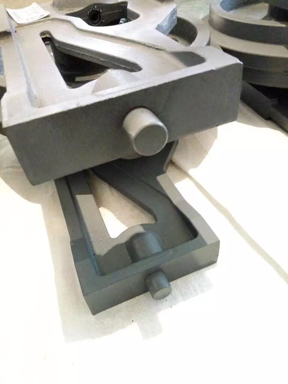
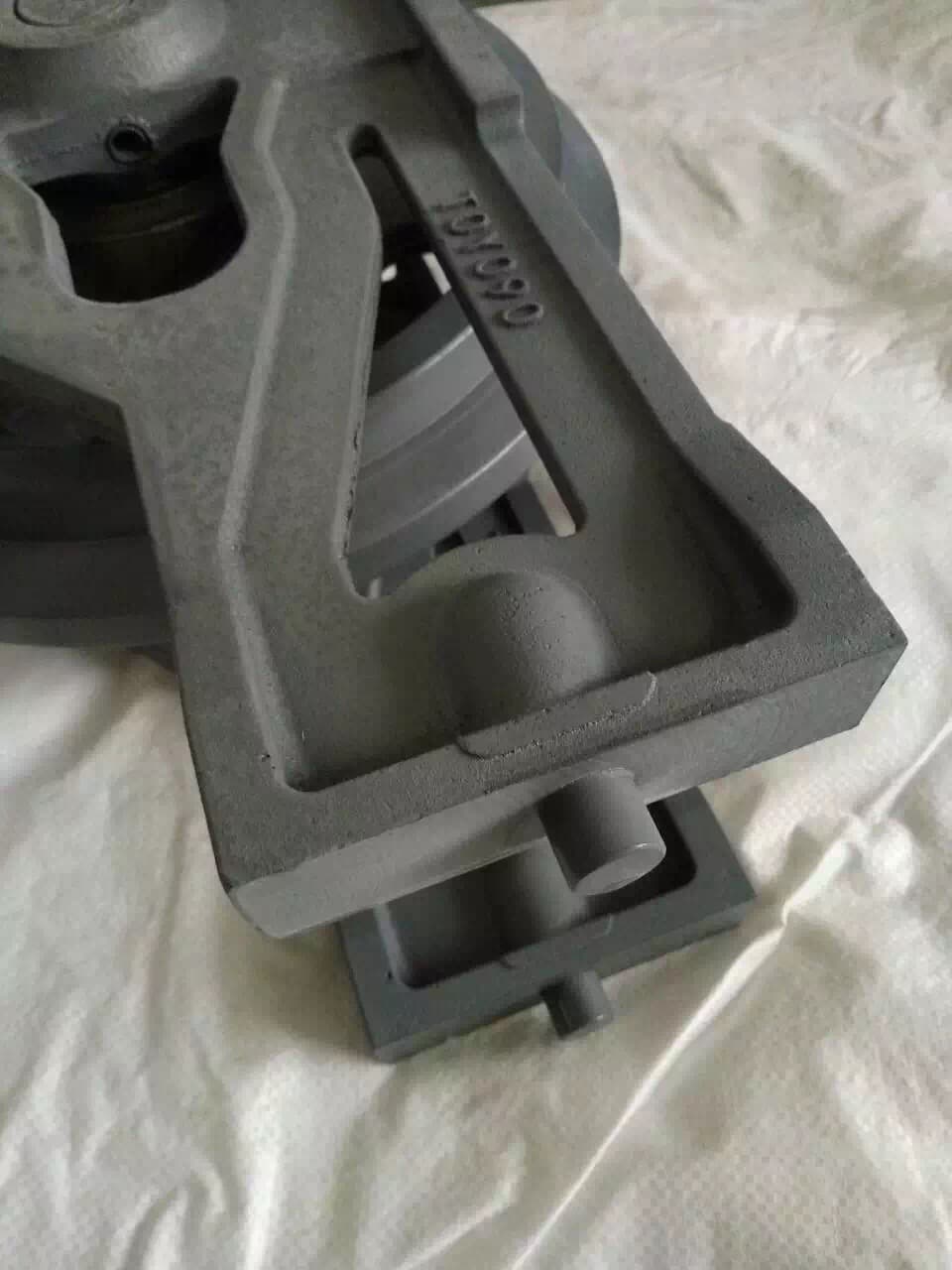
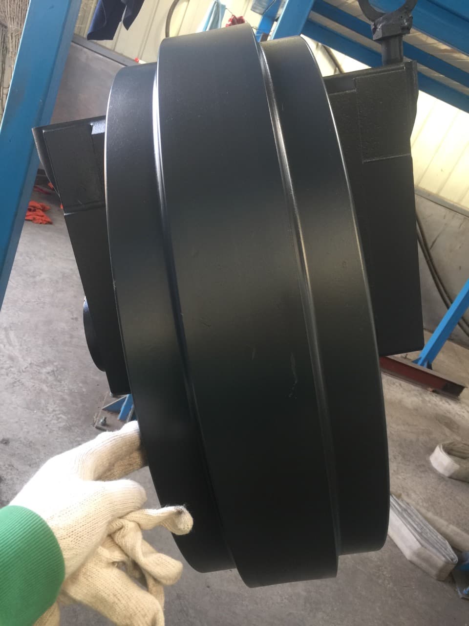
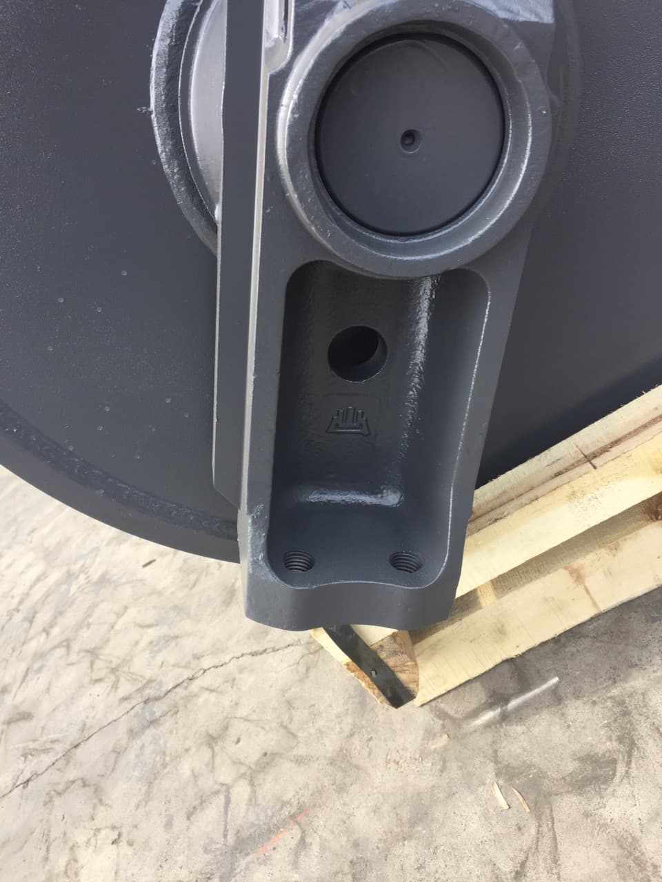
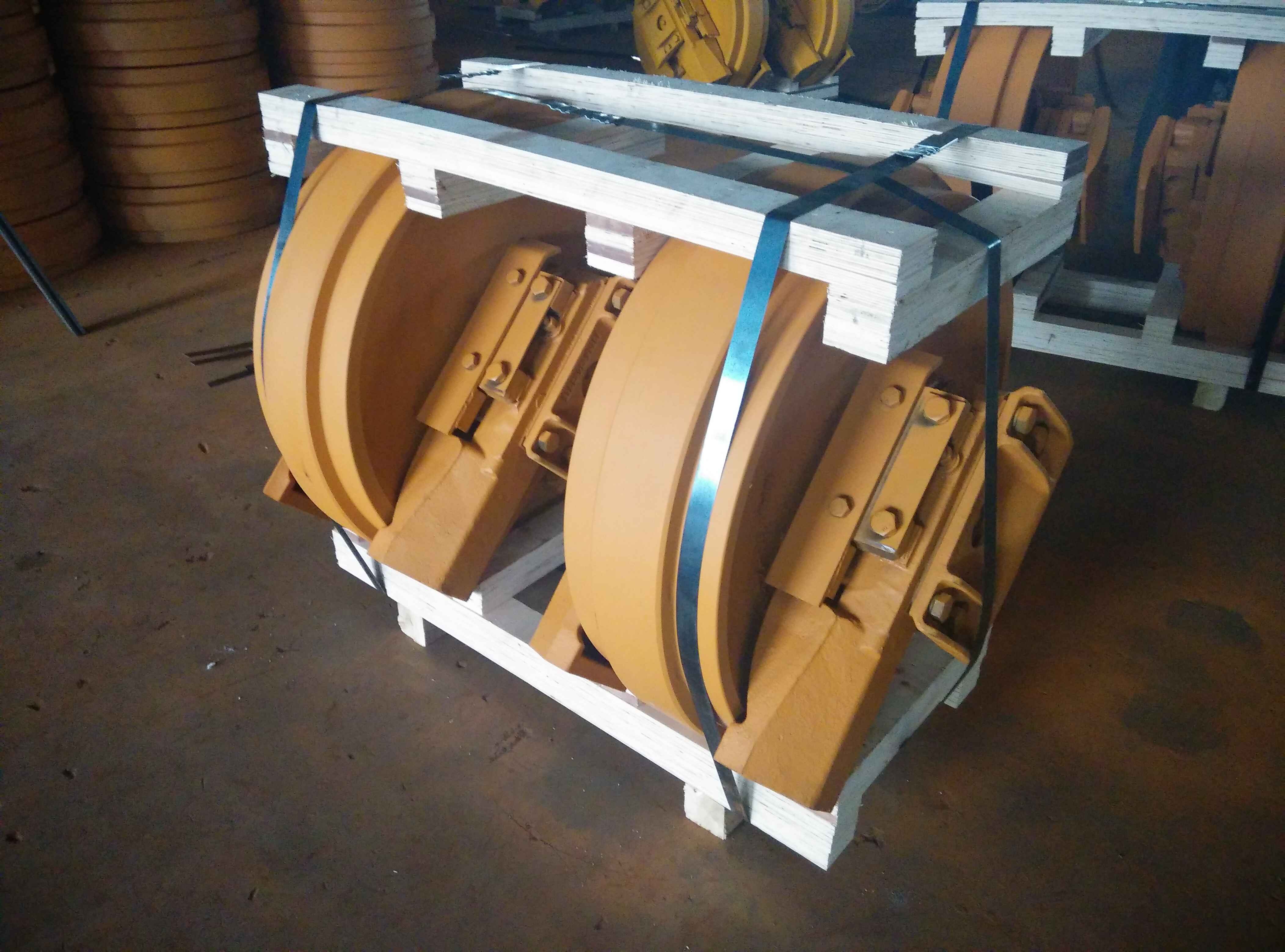
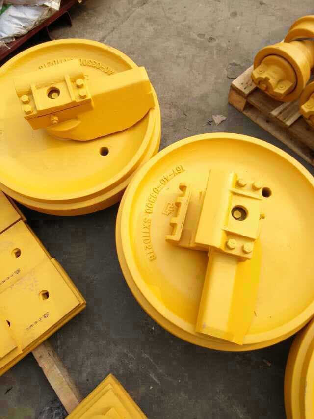
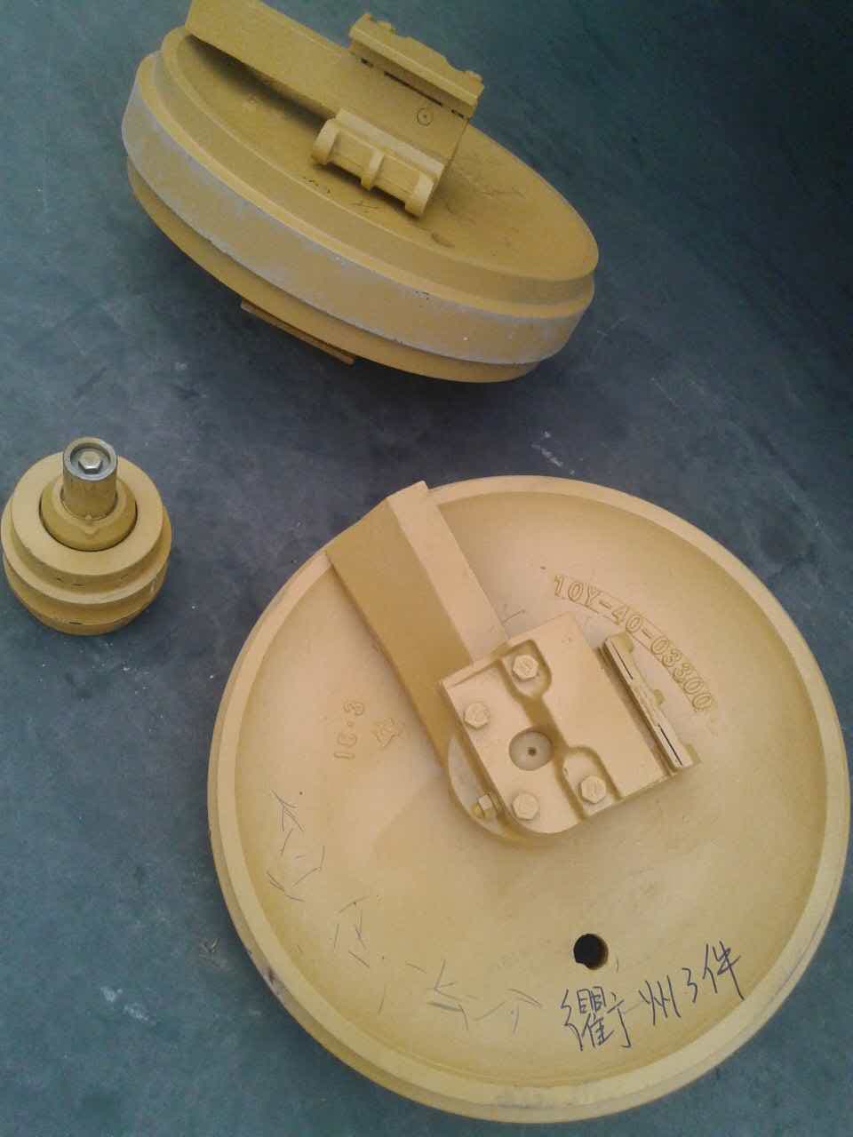
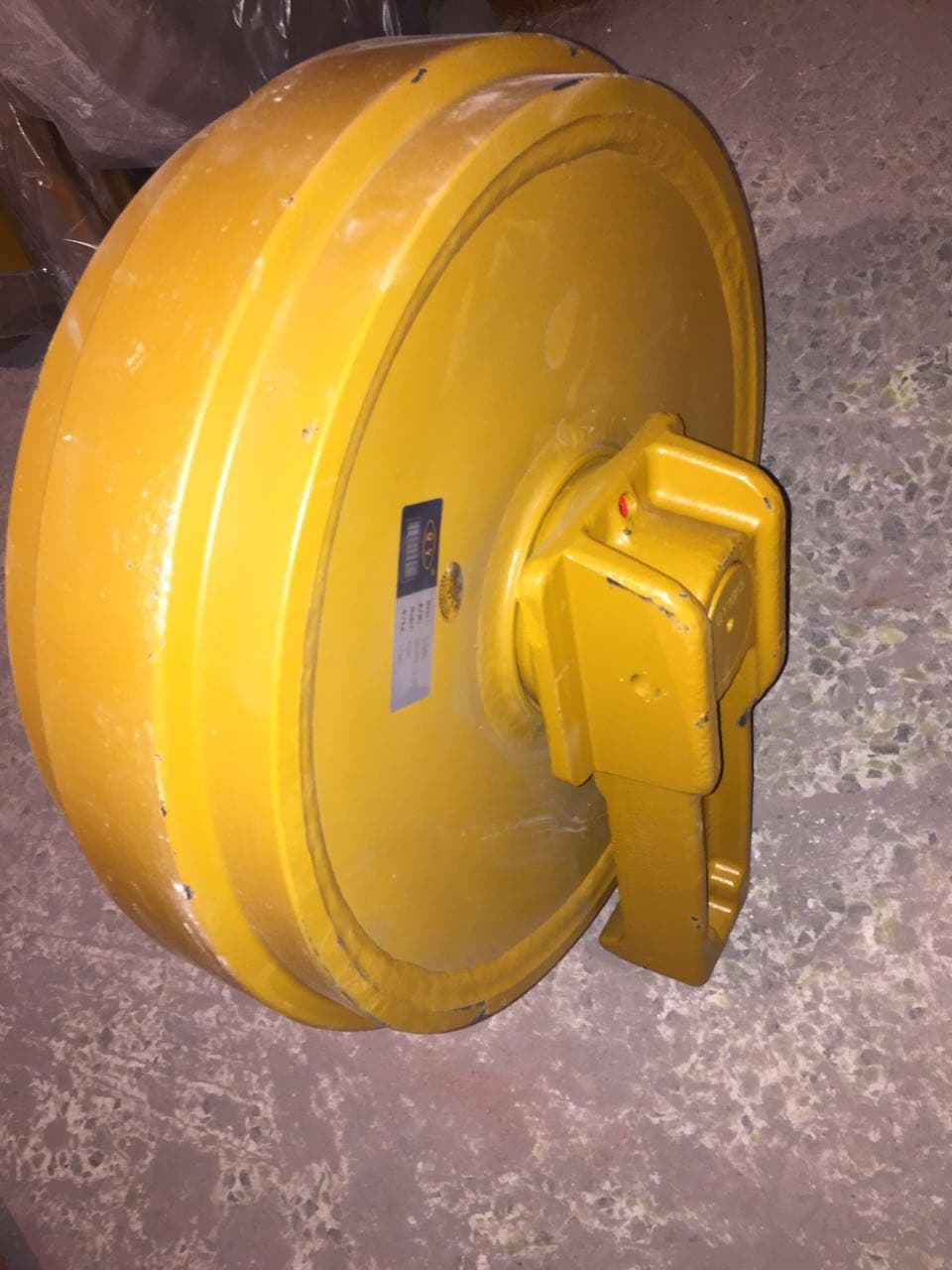
FY Machinery brings together undercarriage manufacturing and international supply. Compare idler mounting arrangements and published dimensions, then send your machine model, part number, photos and drawing for confirmation and quotation.
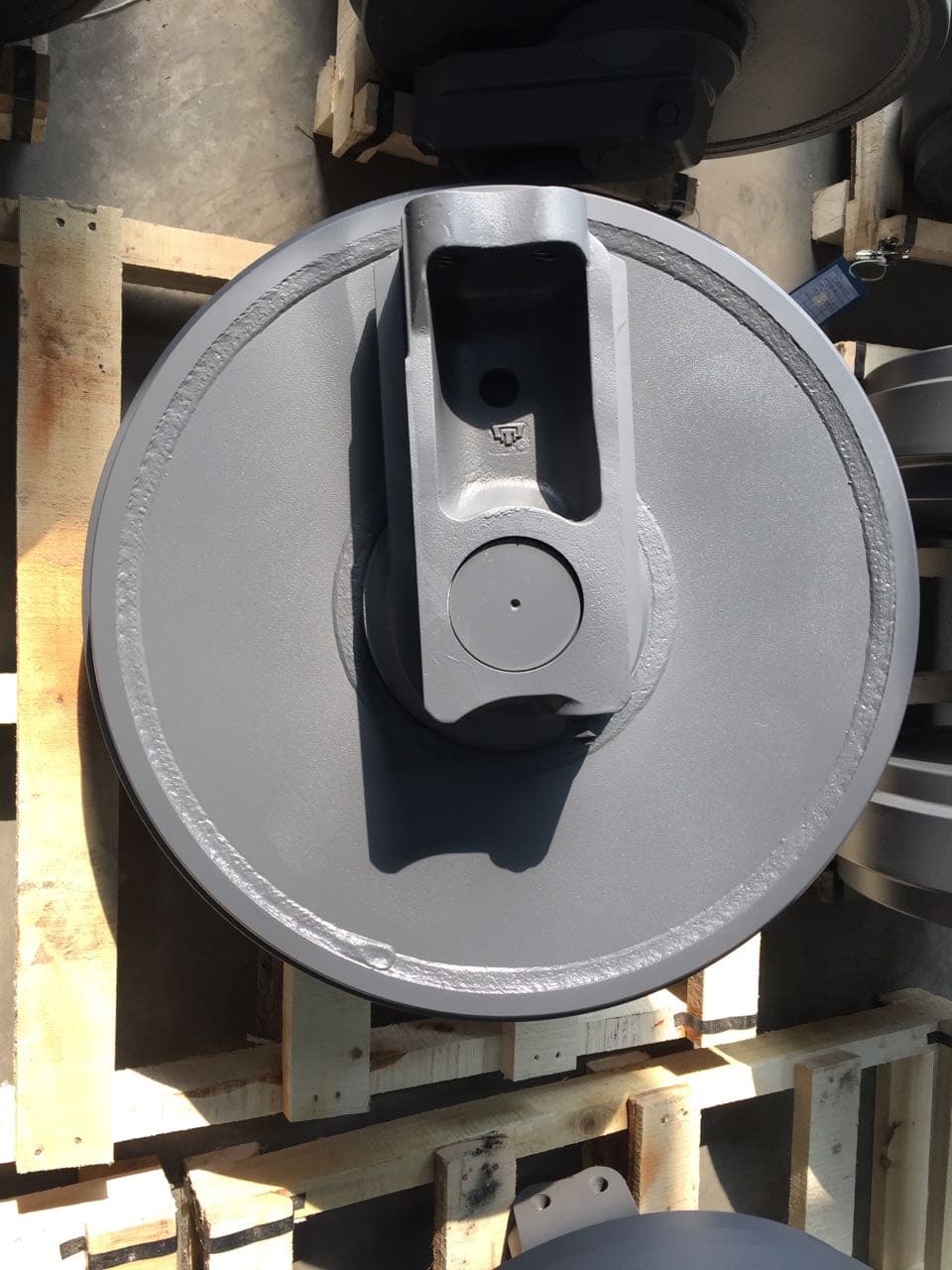
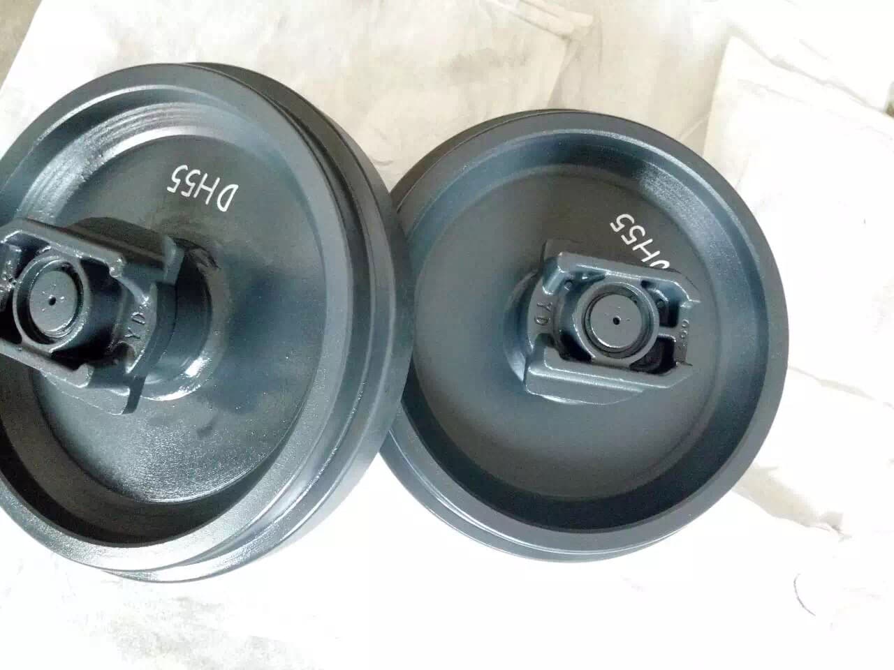
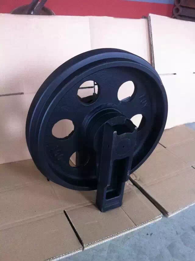
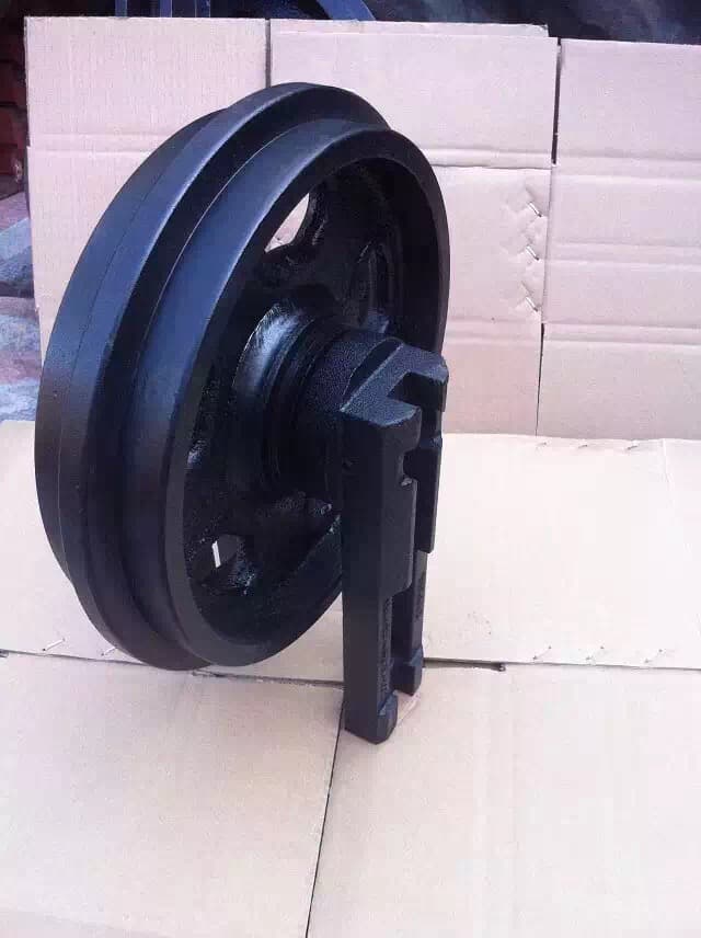
An idler guides the track path as the track chain travels around the undercarriage. It works in relation to the track chains, track rollers, and the front-idler and track-adjuster tensioning arrangement where applicable to the machine.
Excavator Application
Excavator Idler Context
An excavator idler is reviewed as part of the machine's complete track path and front-idler or track-adjuster arrangement. Matching depends on the specific machine and supplied references, not unsupported brand or model assumptions.
A bulldozer idler also guides the track path within the wider undercarriage arrangement. The required position, interfaces, and requested supply scope should be confirmed for the specific machine.
The idler guides the path followed by the track chain, so chain condition and configuration can provide useful context when identifying a replacement idler.
The front-idler position may relate to the machine's track-adjuster and tensioning arrangement. Share this relationship when requesting product matching.
Choose the confirmation method by the actual bracket and mounting arrangement. Wheel appearance alone is insufficient: compact, standard and heavy mounting configurations require different measurements.
Machine Model → Part Number → Mounting Arrangement → Mounting Dimensions → Drawing
Welded or 1 bolt per side
Compact / Special Mounting
Some small-machine brackets are welded or have one bolt hole per side. Start with the machine model and part number, because these structures vary.
For the single-hole arrangement, measure between the two opposing hole centers (1). For a welded bracket, provide the key bracket / mounting-center spacing on a marked photo or drawing; the bolted sketch does not define the welded interface.
FY measurement-method schematic · Not to scale. Numbers explain measurement directions; they are separate from the dimension letters below.
4 mounting bolts in total
Standard 2-Bolt-per-Side Mounting
The most common arrangement uses two holes on each bracket. Confirm the machine model and part number, then record the four-hole mounting pattern.
Measure center to center in both directions: between the two brackets (1), and between the two holes on each bracket (2). Add hole diameter if needed. Record both directions rather than a diagonal.
FY measurement-method schematic · Not to scale. Numbers explain measurement directions; they are separate from the dimension letters below.
8 mounting bolts in total
Heavy 4-Bolt-per-Side Mounting
Larger brackets use four holes per side. Confirm the center distances between the opposing hole groups and the pattern within each bracket.
Record the spans between brackets (1), including each opposing column, and the two directions within each four-hole group (2 / 3). Send a drawing for exact confirmation.
FY measurement-method schematic · Not to scale. Numbers explain measurement directions; they are separate from the dimension letters below.
Use a drawing for precise or special requirements
For every idler type, a drawing is the most reliable basis for exact confirmation. Send photos of both brackets, the machine model, part number and mounting dimensions in millimetres. Show the measurement points and specify whether you need the wheel or a wider assembly.
Type I / II / III dimension guide
Type labels group the published technical references. These illustrated bolted configurations have one, two and four holes per bracket respectively. Compact welded arrangements require their own drawing and are not assigned a Type by this guide. The schematics explain dimension references; they are not engineering or acceptance drawings.
FY dimension reference
Type I
Two mounting bolts in the published references
FY original schematic · Not to scale · A / B: wheel diameter references; C–E: axial profile widths; G: overall axial width. F: opposing mounting-hole centers; I / J: bracket references. K: total mounting-bolt count × thread specification. Confirm exact points and tolerances with a drawing.
FY dimension reference
Type II
Four mounting bolts in the published references
FY original schematic · Not to scale · A / B: wheel diameter references; C–E: axial profile widths; G: overall axial width. F: opposing mounting-hole centers; I / J: bracket references. K: total mounting-bolt count × thread specification. Confirm exact points and tolerances with a drawing.
FY dimension reference
Type III
Eight mounting bolts · separate F1 / F2 hole-center distances
Read F1 and F2 separately
F1 spans the inner opposing hole columns; F2 spans the outer opposing hole columns in this axial view. Both published Type III rows show F1 = 322 mm and F2 = 466 mm.
Also confirm the four-hole pattern within each bracket. The reference figure does not locate H, I and J for Type III; their table values are retained, and their exact measurement points must be checked on the product drawing.
FY original schematic · Not to scale · A / B: wheel diameter references; C–E: axial profile widths; G: overall axial width. F1 / F2: separate hole-center spans. K: total mounting-bolt count × thread specification. Confirm exact points and tolerances with a drawing.
Published Reference Data
Idler Specifications
All 10 published references are grouped by Type I, II and III for dimensional comparison. Model references are not exhaustive and are intentionally omitted, so this table does not define FY’s machine coverage. Final idler selection should be confirmed using the machine model, part number, drawing and mounting dimensions.
Weight in kg · Dimensions in mm · Mounting (K) = total bolt count × thread specification · Type III uses separate F1 and F2 fields · 0 is a supplied value; — means not provided. Technical data is shown for reference and dimensional comparison; confirm the specific product drawing before ordering.
Type I · 2 references
Two mounting bolts in the published references
Type I idler published reference specifications
Code
Type
Weight (kg)
Key Dimensions (mm)
Mounting (K)
HWY135A
I
47.84
A
340
B
372
C
53
D
110
E
160
F
205
G
240
H
0
I
60
J
170
2×M16
HWY154B
I
62.00
A
415
B
445
C
51
D
112
E
160
F
205
G
240
H
0
I
60
J
190
2×M16
HWY135AType I · 47.84 kg · 2×M16+
A
340
B
372
C
53
D
110
E
160
F
205
G
240
H
0
I
60
J
170
Mounting (K): 2×M16
Dimensions in mm. Confirm final selection using the machine model, part number, drawing and mounting dimensions.
HWY154BType I · 62.00 kg · 2×M16+
A
415
B
445
C
51
D
112
E
160
F
205
G
240
H
0
I
60
J
190
Mounting (K): 2×M16
Dimensions in mm. Confirm final selection using the machine model, part number, drawing and mounting dimensions.
Type II · 6 references
Four mounting bolts in the published references
Type II idler published reference specifications
Code
Type
Weight (kg)
Key Dimensions (mm)
Mounting (K)
HWY154A
II
58.24
A
415
B
460
C
43
D
100
E
156
F
200
G
240
H
40
I
73
J
242
4×M14
HWY175A
II
70.00
A
489
B
527
C
52
D
115
E
183.1
F
227
G
263
H
44
I
78
J
302
4×M14
HWY190A
II
121.04
A
520
B
560
C
85
D
164
E
247.4
F
280
G
336
H
66
I
105
J
196
4×M16
HWY190B
II
125.00
A
547
B
506
C
82
D
158
E
203.8
F
270
G
343.8
H
60
I
115
J
—
4×M16
HWY216A
II
184.76
A
590
B
635
C
101
D
190
E
261
F
360
G
404
H
60
I
120
J
250
4×M20
HWY228A
II
259.41
A
660
B
704
C
106
D
202
E
297
F
410
G
462
H
66
I
145
J
275
4×M24
HWY154AType II · 58.24 kg · 4×M14+
A
415
B
460
C
43
D
100
E
156
F
200
G
240
H
40
I
73
J
242
Mounting (K): 4×M14
Dimensions in mm. Confirm final selection using the machine model, part number, drawing and mounting dimensions.
HWY175AType II · 70.00 kg · 4×M14+
A
489
B
527
C
52
D
115
E
183.1
F
227
G
263
H
44
I
78
J
302
Mounting (K): 4×M14
Dimensions in mm. Confirm final selection using the machine model, part number, drawing and mounting dimensions.
HWY190AType II · 121.04 kg · 4×M16+
A
520
B
560
C
85
D
164
E
247.4
F
280
G
336
H
66
I
105
J
196
Mounting (K): 4×M16
Dimensions in mm. Confirm final selection using the machine model, part number, drawing and mounting dimensions.
HWY190BType II · 125.00 kg · 4×M16+
A
547
B
506
C
82
D
158
E
203.8
F
270
G
343.8
H
60
I
115
J
—
Mounting (K): 4×M16
J: not provided in the reference data; confirm with a drawing.
Dimensions in mm. Confirm final selection using the machine model, part number, drawing and mounting dimensions.
HWY216AType II · 184.76 kg · 4×M20+
A
590
B
635
C
101
D
190
E
261
F
360
G
404
H
60
I
120
J
250
Mounting (K): 4×M20
Dimensions in mm. Confirm final selection using the machine model, part number, drawing and mounting dimensions.
HWY228AType II · 259.41 kg · 4×M24+
A
660
B
704
C
106
D
202
E
297
F
410
G
462
H
66
I
145
J
275
Mounting (K): 4×M24
Dimensions in mm. Confirm final selection using the machine model, part number, drawing and mounting dimensions.
Type III · 2 references
Eight mounting bolts · separate F1 / F2 hole-center distances
Type III idler published reference specifications
Code
Type
Weight (kg)
Key Dimensions (mm)
Mounting (K)
HWY260A
III
520.00
A
783
B
828
C
127
D
266
E
338
F1
322
F2
466
G
520
H
120
I
180
J
402
8×M20
HWY260B
III
560.00
A
840
B
885
C
127
D
266
E
338
F1
322
F2
466
G
520
H
120
I
180
J
430
8×M20
HWY260AType III · 520.00 kg · 8×M20+
A
783
B
828
C
127
D
266
E
338
F1
322
F2
466
G
520
H
120
I
180
J
402
Mounting (K): 8×M20
Dimensions in mm. Confirm final selection using the machine model, part number, drawing and mounting dimensions.
HWY260BType III · 560.00 kg · 8×M20+
A
840
B
885
C
127
D
266
E
338
F1
322
F2
466
G
520
H
120
I
180
J
430
Mounting (K): 8×M20
Dimensions in mm. Confirm final selection using the machine model, part number, drawing and mounting dimensions.
Most FY idler wheel bodies use 40Mn2 steel, with forging as the main forming process. Confirm the material and forming requirements for the specific idler specification.
Quenching & typical hardness
Idler wheel bodies are quenched, with a typical hardness range of HRC45–52 for applicable specifications. Special material or heat-treatment requirements should be stated with the inquiry and checked against the drawing.
Assembly & inspection requirements
Confirm the applicable sealing, lubrication and inspection requirements for the specific assembly during quotation review. Share the drawing and any special requirements together with the mounting dimensions.
Product Configuration
Idler terminology and assembly scope
Buyer and supplier terminology can vary. Front idler, track idler, and idler wheel may describe the undercarriage idler, while idler assembly can indicate a wider supply scope that must be confirmed for the specific machine.
01
Buyer Terminology
Front Idler
Front idler commonly describes the undercarriage idler at the front of the track frame. Confirm the actual machine position and arrangement rather than relying on the term alone.
02
Buyer Terminology
Track Idler
Track idler may be used by buyers or suppliers for the idler that guides the undercarriage track path. Machine and interface references are still needed for matching.
03
Buyer Terminology
Idler Wheel
Idler wheel may describe the same general undercarriage component in commercial conversation, but the required configuration should be checked against the machine.
04
Supply Scope
Idler Assembly
Idler assembly may refer to a wider set of supplied items than the idler wheel alone. The included scope varies and should be stated explicitly rather than treated as an unconditional synonym.
Product Identification
Information for replacement idler matching
A clear reference set helps FY Machinery review product matching and prepare a more useful B2B quotation without assuming fitment from appearance alone.
Provide the manufacturer name and complete model designation shown in the machine records or on the identification plate.
02
Available part number
Share the part number if known, together with where it was found, such as the existing idler, parts documentation, or a previous purchase record.
03
Clear idler photos
Send clear overall and close-up photos, including side views, interface areas, visible markings, and the installed context when practical.
04
Requested measurements and interfaces
Identify welded, single-hole, two-hole-per-side or four-hole-per-side mounting. Provide the relevant hole-center or bracket-center distances in millimetres, plus hole diameter when needed. For precise or special requirements, send a drawing with the measurement points.
05
Adjuster and front-idler relationship
Show or describe how the idler relates to the track-adjuster, tensioning arrangement, track frame, and track path on the machine.
06
Assembly scope and quantity
State whether the request is for an idler wheel or a wider idler assembly, list any known included items, and confirm the required quantity.
Order Review & Packing
Inspection clues and supplier support
Visible wear or damage, abnormal movement, misalignment, unusual contact, leakage where visible, or irregular track guidance can justify closer inspection. These are high-level clues, not universal replacement limits or repair instructions; assessment must follow the specific machine and qualified inspection.
Visible wear or surface damage
Check for clearly visible wear, damaged areas, or cracked surfaces and record the location with overall and close-up photos.
Movement and alignment clues
Abnormal movement, apparent misalignment, or a changed idler position can indicate that the wider arrangement needs inspection.
Contact and track guidance
Unusual contact marks, interference, or irregular guidance of the track path are useful observations to document for review.
Visible leakage
Where leakage is visible around the idler area, photograph the location and surrounding arrangement without assuming a universal cause or repair method.
Product matching and direct quotation
FY Machinery reviews the supplied references for product matching and prepares quotations based on confirmed requirements.
Quality, order, and visit follow-up
Confirmed requirements support order-specific quality follow-up and order coordination. Production-site visits can be coordinated where appropriate and agreed.
Buyer Questions
Idler buyer FAQ
What is an excavator idler?+
An excavator idler is an undercarriage component that guides the track path. It works in relation to the track chain, track rollers, and the machine's front-idler and track-adjuster tensioning arrangement.
Is a front idler the same as a track idler?+
The terms often describe the undercarriage idler in buyer or supplier terminology, especially the idler at the front of the track frame. Confirm the actual position, machine, and configuration because terminology alone does not establish fitment.
What does idler assembly mean?+
Idler assembly can describe a wider supply scope than the idler wheel alone. The exact included items can vary, so buyers should confirm the requested assembly scope for the specific machine.
How do I know when an idler should be inspected?+
Visible wear, damaged or cracked surfaces, abnormal movement, misalignment, unusual contact, visible leakage, or irregular track guidance are reasons for closer inspection. They are not universal replacement limits or repair instructions.
What information helps match a replacement idler?+
Send the machine make and model, part number if known, clear photos of the idler and both brackets, mounting arrangement and center distances in millimetres, drawing, requested assembly scope and quantity. Include the track-adjuster relationship where relevant; a drawing is the most reliable basis for precise or special confirmation.
Send an Inquiry
Request a replacement idler quotation
Send your machine model, part number, photos of both brackets, mounting dimensions and drawing, together with assembly scope and quantity. Include front-idler and track-adjuster context where relevant. FY Machinery will review the references for product matching and quotation.