Undercarriage Role
Drive Component
The drive component works with the applicable track chain as part of the wider undercarriage. Its teeth engage the chain to transmit drive through the track system.
Undercarriage Drive Components
FY Machinery brings together undercarriage manufacturing, our factory and international sales. Explore complete excavator sprockets and bulldozer sprocket segments, then confirm your part number, tooth count and mounting dimensions with our team.
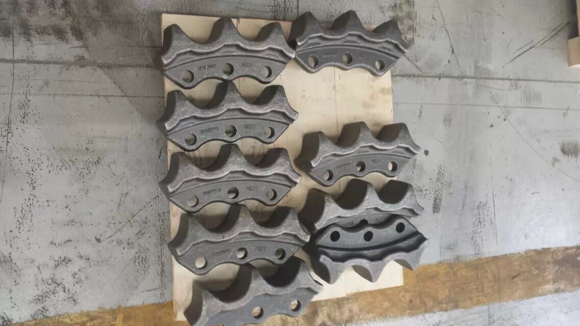
Product & Terminology Guide
At a high level, the drive sprocket engages the applicable track chain and transmits drive through the undercarriage. Clear parts terminology matters because a general sprocket description and one sprocket segment do not define the same supply scope.
Undercarriage Role
The drive component works with the applicable track chain as part of the wider undercarriage. Its teeth engage the chain to transmit drive through the track system.
General Parts Language
Sprocket or Drive Sprocket may describe the undercarriage drive component in general buyer terminology. The term alone does not establish whether the actual arrangement is complete or segmented.
Segmented Configuration
A sprocket segment is one section used in a segmented drive arrangement. It must not be treated as an unconditional synonym for a complete sprocket.
Excavator Application
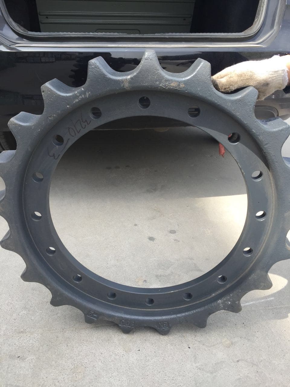
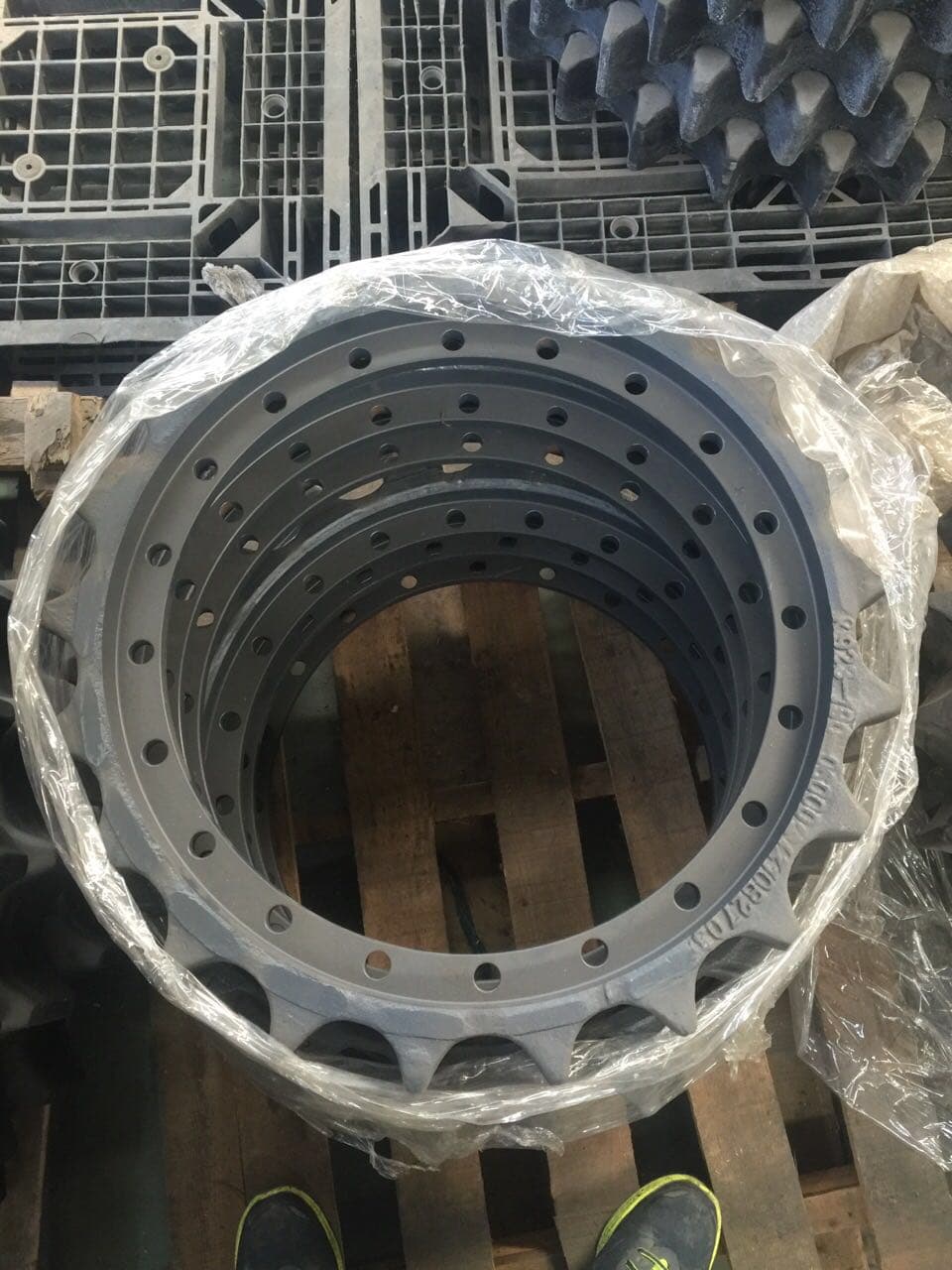
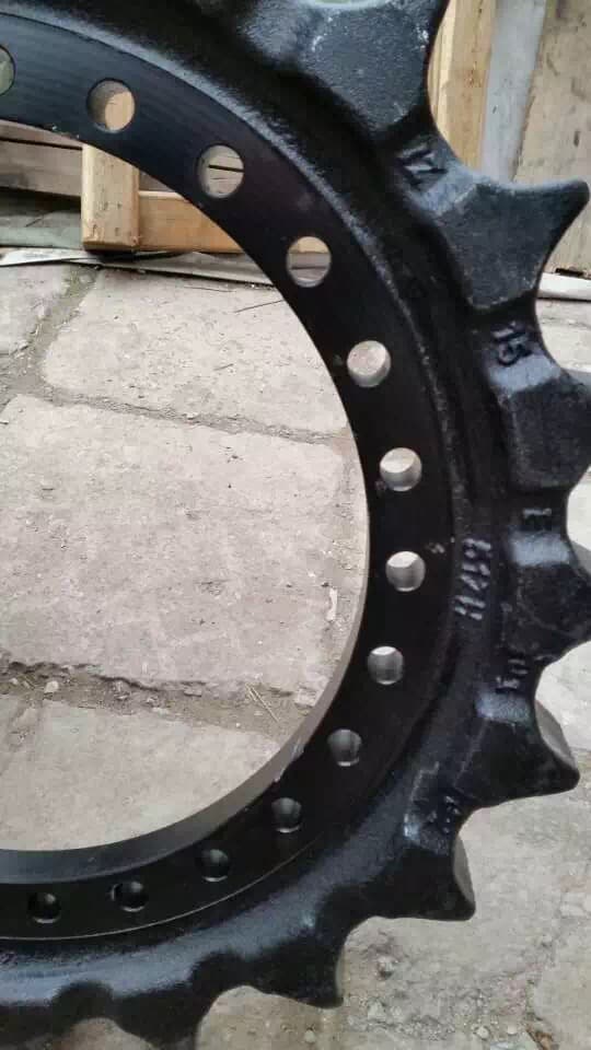
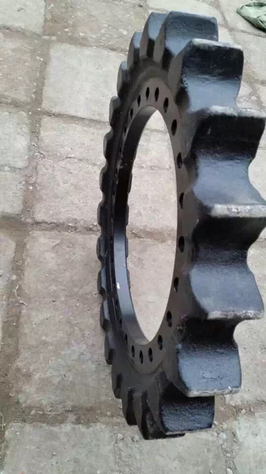
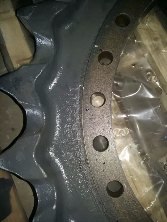
Excavators typically use a complete toothed sprocket disc. Confirm the machine model and part number, then tooth count, bolt-hole pattern, bore and key mounting dimensions against the drawing.
View Excavator Undercarriage PartsBulldozer Application
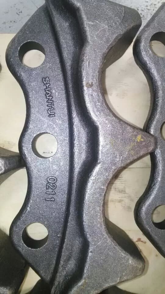
Bulldozers typically use multiple toothed segments assembled around a complete circle. Confirm the model, part number or segment marking, teeth and bolt holes per segment, and drawing.
View Bulldozer Undercarriage PartsComplete drive component
Excavators typically use a complete toothed sprocket disc. Its tooth count, bolt-hole pattern and bore must match the specific mounting arrangement. The following references describe complete sprockets.
Machine Model → Part Number → Number of Teeth → Bolt Holes → Bore / Key Mounting Dimensions → Drawing
01
Start with the complete machine make and model from the identification plate or machine records.
02
Share the sprocket part number from the existing part, parts book or a reliable purchase record.
03
Count the teeth on the complete sprocket. A matching model name alone is insufficient.
04
Count the bolt holes and measure their diameter. Include the hole-center circle or other mounting references where needed.
05
Measure the inner diameter and key mounting dimensions in mm; show the measurement points on a photo or drawing.
06
Use the corresponding drawing for final dimensional confirmation. Special specifications require a drawing.
For a special specification, send the drawing at the start of the inquiry. Photos of the teeth, both faces, bore and mounting area help explain the request.
Type labels distinguish the published side profiles; they are not manufacturing routes. Read A–J with the corresponding schematic and K as the bolt-hole pattern. Tooth and hole counts in the figures are illustrative; each specification row gives its actual counts.
FY dimension reference
Side profile and face view · Confirm the type and mounting profile on the specific drawing.
Side profile · A–I
Face view · J / K
FY original schematic · Not to scale · A: bore / inner diameter; D: bolt-hole center-circle reference; B / C / E / F: radial profile references; G / H: axial mounting-profile references; I: rim width; J: tooth-spacing reference. K specifies the bolt-hole pattern, while the number of teeth is a separate field. These figures explain the data letters; use the product drawing for exact measurement points and tolerances.
Published reference data
All 14 references are retained in seven code families: 135 / 154 / 175 / 190 / 216 / 228 / 260. A family may include different types, bore dimensions or bolt patterns. Family numbers group the codes; use the actual J value shown in each row for dimensional comparison.
Weight in kg · A–J dimensions in mm · Bolt Pattern (K) = number of holes × hole diameter in mm (for example, 12×φ15 means 12 holes of 15 mm diameter) · No. of Teeth is listed separately.
Bolt Pattern (K): 12×φ15 · No. of Teeth: 19
Dimensions in mm. Confirm the machine model, part number, tooth count, bolt pattern, bore dimensions and drawing before ordering.
Bolt Pattern (K): 12×φ16 · No. of Teeth: 21
Dimensions in mm. Confirm the machine model, part number, tooth count, bolt pattern, bore dimensions and drawing before ordering.
Bolt Pattern (K): 12×φ15 · No. of Teeth: 21
Dimensions in mm. Confirm the machine model, part number, tooth count, bolt pattern, bore dimensions and drawing before ordering.
Bolt Pattern (K): 15×φ18 · No. of Teeth: 21
Dimensions in mm. Confirm the machine model, part number, tooth count, bolt pattern, bore dimensions and drawing before ordering.
Bolt Pattern (K): 22×φ17 · No. of Teeth: 21
Dimensions in mm. Confirm the machine model, part number, tooth count, bolt pattern, bore dimensions and drawing before ordering.
Bolt Pattern (K): 30×φ17 · No. of Teeth: 21
Dimensions in mm. Confirm the machine model, part number, tooth count, bolt pattern, bore dimensions and drawing before ordering.
Bolt Pattern (K): 24×φ21 · No. of Teeth: 21
Dimensions in mm. Confirm the machine model, part number, tooth count, bolt pattern, bore dimensions and drawing before ordering.
Bolt Pattern (K): 20×φ26 · No. of Teeth: 21
Dimensions in mm. Confirm the machine model, part number, tooth count, bolt pattern, bore dimensions and drawing before ordering.
Bolt Pattern (K): 20×φ26 · No. of Teeth: 21
Dimensions in mm. Confirm the machine model, part number, tooth count, bolt pattern, bore dimensions and drawing before ordering.
Bolt Pattern (K): 24×φ26 · No. of Teeth: 23
Dimensions in mm. Confirm the machine model, part number, tooth count, bolt pattern, bore dimensions and drawing before ordering.
Bolt Pattern (K): 40×φ22 · No. of Teeth: 23
Dimensions in mm. Confirm the machine model, part number, tooth count, bolt pattern, bore dimensions and drawing before ordering.
Bolt Pattern (K): 36×φ22 · No. of Teeth: 23
Dimensions in mm. Confirm the machine model, part number, tooth count, bolt pattern, bore dimensions and drawing before ordering.
Bolt Pattern (K): 26×φ26 · No. of Teeth: 21
Dimensions in mm. Confirm the machine model, part number, tooth count, bolt pattern, bore dimensions and drawing before ordering.
Bolt Pattern (K): 30×φ29 · No. of Teeth: 25
Dimensions in mm. Confirm the machine model, part number, tooth count, bolt pattern, bore dimensions and drawing before ordering.
Technical data is shown for dimensional comparison. Machine-model references are intentionally omitted because the source references are not exhaustive and do not define FY’s machine coverage. Final selection requires confirmation of the machine model, part number, tooth count, bolt pattern, bore dimensions and drawing.
Reference values are retained as supplied, including E = F = 870 mm for HWQ260-2A. Confirm these profile dimensions on the specific drawing before ordering.
Individual sections · assembled around a circle
Bulldozers typically use multiple toothed segments assembled to form a complete circumference. A segment is an individual section. Confirm the requirements per segment and state whether the quantity is for individual pieces or complete sets.
Machine Model → Part Number / Segment Marking → Teeth per Segment → Bolt Holes per Segment → Drawing
Start with the machine model and part number. Most segments carry an identification number or marking; send a clear close-up of any visible marking together with overall photos.
Confirm the teeth per segment and bolt holes per segment. Add hole diameter and key mounting measurements where available. Whole-circle counts do not replace the counts for each piece.
A drawing is the most reliable basis for checking the segment profile and mounting arrangement. Share it with the markings, photos, required pieces or sets and quantity.
Segment dimensions are confirmed by inquiry. No segment specification table is published here; the complete-sprocket data above does not describe individual segments.
Send Segment RFQ →Product Media
Machine Application
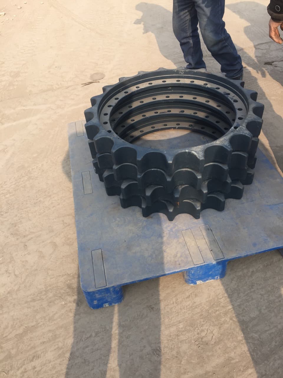
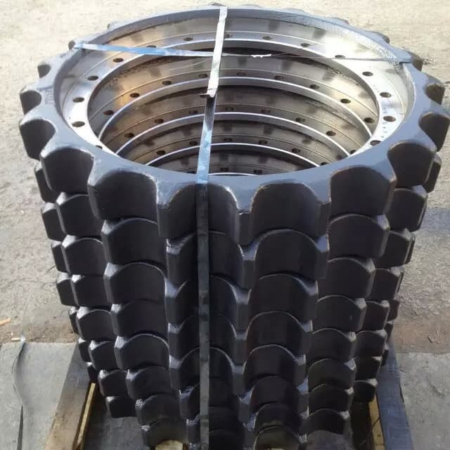
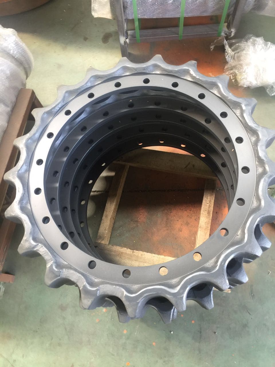
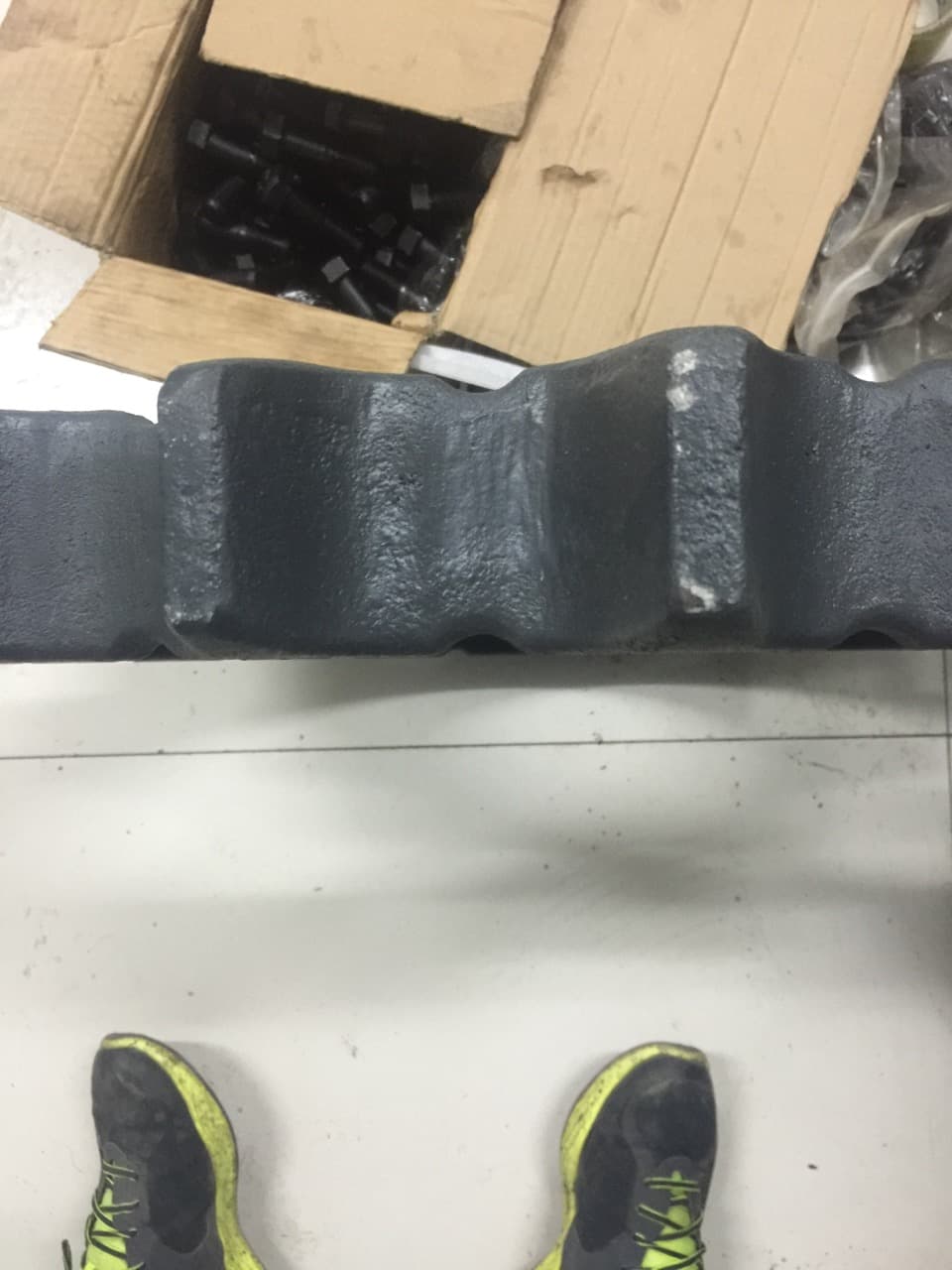
Machine Application
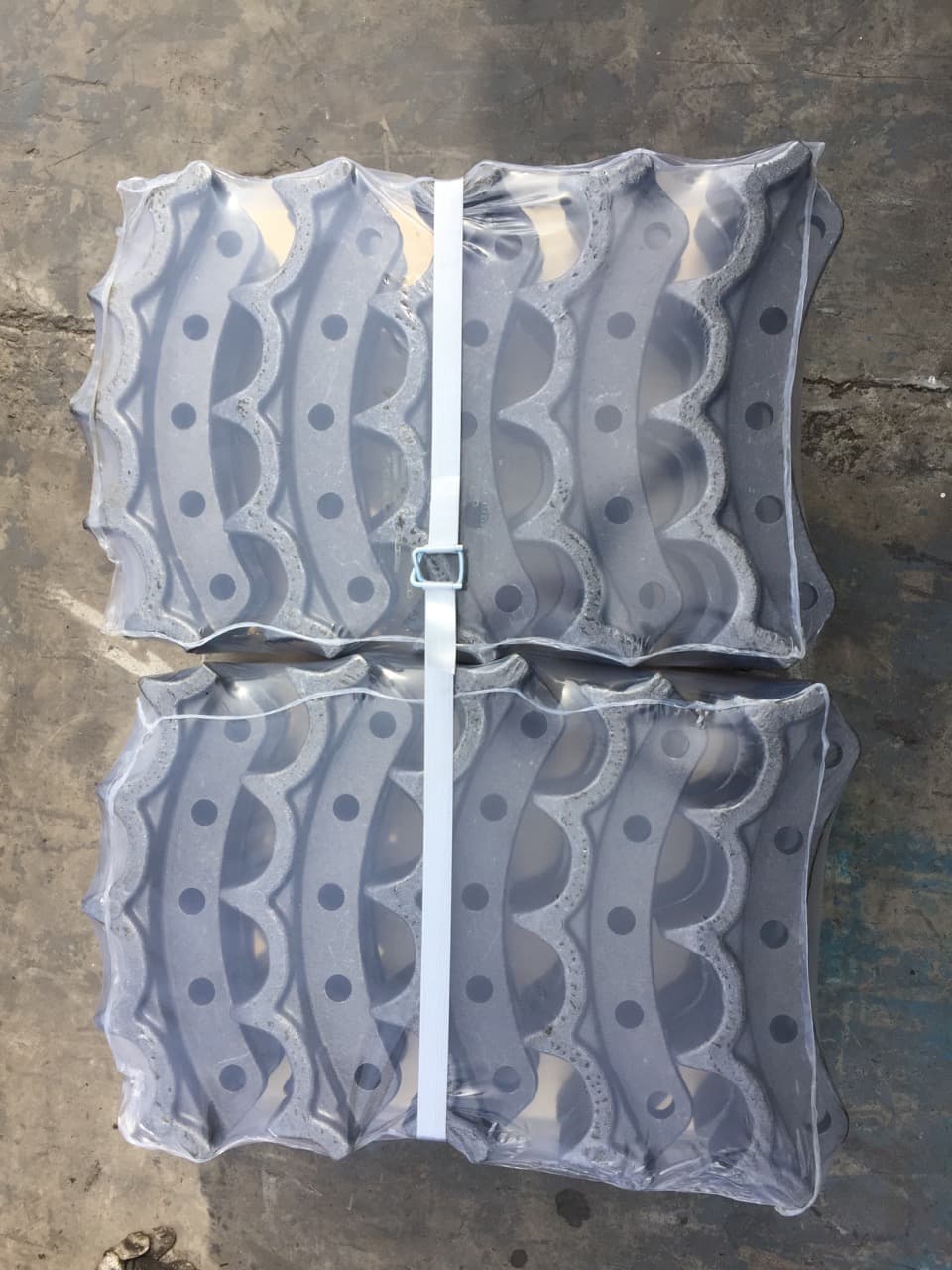
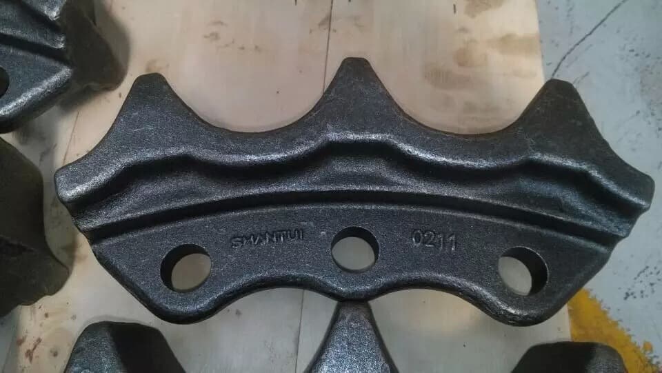
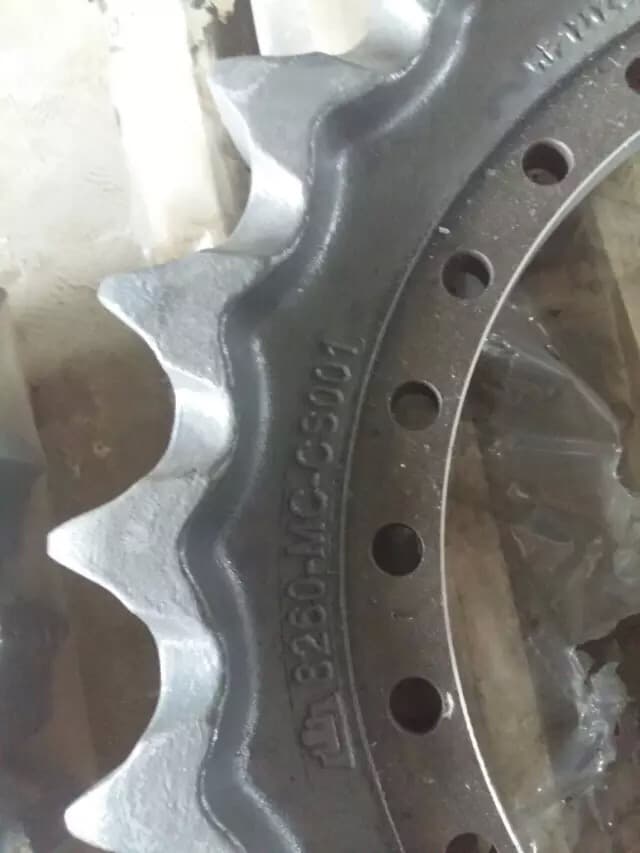
Inspection Clues
Visible or operating concerns can justify qualified inspection of the sprocket, sprocket segments, track chain, and related undercarriage components. These clues are not universal wear limits or replacement thresholds.
Follow the machine-specific service guidance and use qualified technical judgment. This overview is not a repair instruction or a substitute for inspection of the actual machine.
Replacement-Part Matching
Similar-looking drive components can have different arrangements or interfaces. Send confirmed references instead of relying on appearance, terminology, or one detail alone.
Provide the make and complete model designation shown in the machine records or on the identification plate.
Share a reliable sprocket or segment part number from the existing part, parts book, drawing, or previous purchase record when available.
Send clear overall views plus close-ups of the teeth, mounting or interface areas, markings, and any visible damage or wear.
For a complete sprocket, send tooth count, bolt-hole count and diameter, bore and key mounting dimensions. For a segment, send teeth and bolt holes per piece plus its marking. Show measurement points and units; include the drawing, especially for special specifications.
State whether the request is for a complete sprocket or one or more sprocket segments, and identify the required segment quantity where applicable.
Provide the available track-chain or link reference, photos, and relevant undercarriage context so the drive interface can be reviewed as a system.
State the required quantity clearly and confirm whether it refers to complete sprockets, individual segments, or segment sets.
Manufacturing
Both forged and cast manufacturing routes exist for sprockets and segments. Confirm the route for the specific product specification during quotation and drawing review.
Type I and Type II describe the dimensional profiles in this guide. They do not identify whether a product is forged or cast. State any required manufacturing route with your part number or drawing.
B2B Supply Support
Our manufacturing and international sales teams review the specific sprocket or segment requirements together. Confirmed part references and drawings support product matching, quotation, production coordination and order follow-up.
FY Machinery brings together undercarriage manufacturing, our factory and international sales to review confirmed product and order requirements.
Machine details, part references, photos, requested measurements or interface references, supply scope, chain context, and quantity are reviewed together.
Confirmed product references, quantities, and agreed order requirements support practical quality and order follow-up.
Production-site visits can be coordinated where appropriate to the product, order stage, and agreed arrangement.
Related Undercarriage Parts
Linked components that engage with the applicable drive arrangement.
Lower rollers supporting and guiding the loaded chain path.
Components guiding the track chain around the undercarriage.
Ground-contact components mounted to the track links.
A wider track-system supply scope requiring confirmation.
Buyer Questions
An excavator sprocket is typically a complete toothed disc that engages the track chain to transmit drive. Confirm the machine model, part number, tooth count, bolt-hole pattern, bore and drawing for the specific component.
In general parts language, Sprocket and Drive Sprocket may both describe the undercarriage drive component. The wording alone does not confirm whether the machine uses a complete sprocket or a segmented arrangement, so the actual component and references still need review.
A sprocket segment is one toothed section. Bulldozers typically use several segments assembled to form a complete circumference. Confirm the part number or visible marking, teeth and bolt holes per segment, and drawing.
No. A sprocket segment is part of a segmented arrangement, while a complete sprocket describes the complete drive component requested as one supply scope. Which arrangement applies depends on the machine and undercarriage configuration.
For an excavator sprocket, send the machine model, part number, tooth count, bolt-hole pattern, bore dimensions, photos and drawing. Special specifications require a drawing. For bulldozer segments, send the model, part number or segment marking, teeth and bolt holes per segment, photos, drawing and quantity in pieces or sets.
Request for Quotation
Include the machine model, part number or segment marking, photos, tooth count, bolt-hole pattern, bore and key mounting dimensions, drawing and quantity. For segments, state teeth and bolt holes per piece and whether you need pieces or sets. Special sprocket specifications require a drawing. Add related track-chain references where available.