Assembled Chain
Track Chain
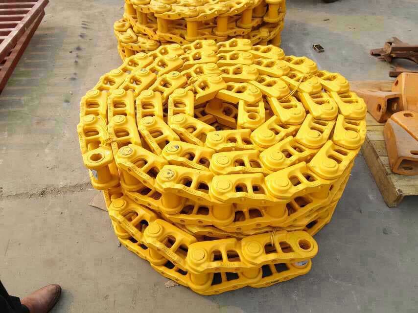
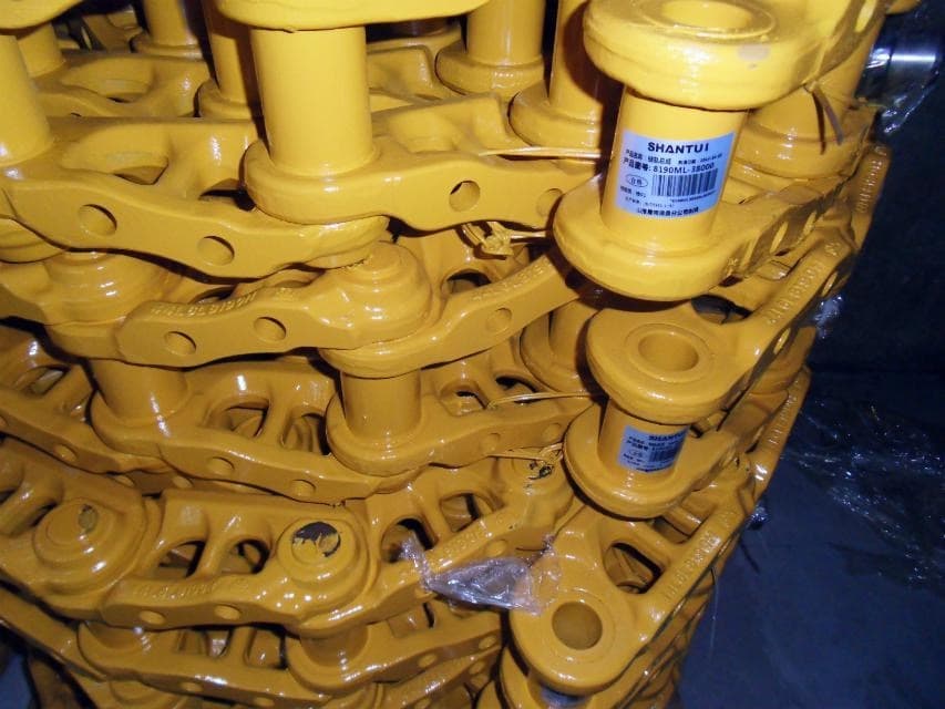
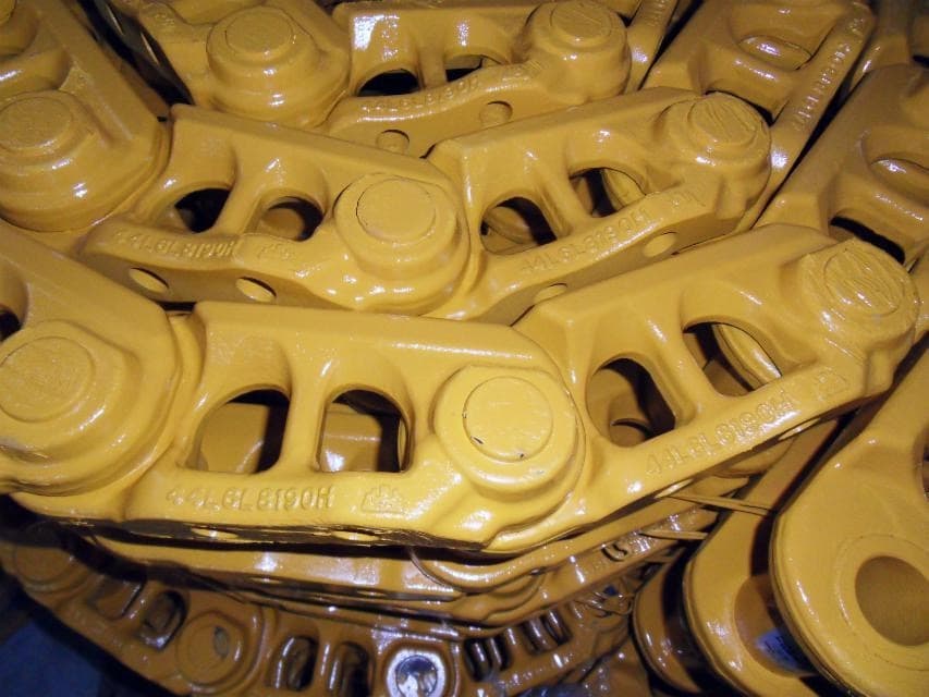
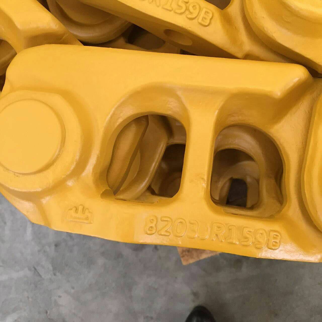
Track Chain refers to the assembled series of connected links. It is the linked running component, not one individual link and not automatically a chain supplied with track shoes.
Linked Undercarriage Components
FY Machinery brings together undercarriage manufacturing and international supply. Match your excavator or bulldozer chain by machine model, part number, pitch, mounting pattern and links per chain, with drawing review for precise requirements.
Product & Terminology Guide
The track chain provides the connected path that carries the track shoes around the undercarriage. It moves along the track rollers and idler and engages the applicable sprocket or segment drive arrangement. Clear terminology helps buyers define which part or assembly they actually need.
Assembled Chain
Track Chain refers to the assembled series of connected links. It is the linked running component, not one individual link and not automatically a chain supplied with track shoes.
Individual Part
Track Links are the individual links within the assembled chain. A Track Link and a Track Chain therefore describe different levels of the linked assembly and are not unconditional synonyms.
Confirm the Meaning
In parts terminology, either name may refer to an assembled chain. Because usage can vary, the requested supply scope must be confirmed from the machine, references, photos, and buyer requirement.
Requested Supply Scope
Confirm whether you need a bare chain or an assembled group with shoes and fastening hardware. Link count per chain and the number of chains or groups are separate quotation details.
Core Scope
A bare track chain means the assembled linked chain without assuming that track shoes or a wider set of track components are included.
Wider Scope
A chain-with-shoes request adds the ground-contact shoes and relevant connection scope. Shoe requirements must be identified for the specific machine.
View Track ShoesConfirmed Combination
A complete track group combines the chain, matched track shoes and fastening bolts/nuts into an assembled system. Confirm both the chain and shoe specifications for the required configuration.
View Complete Track GroupsExcavator Application
An excavator track chain forms the linked running path around the undercarriage. It carries the track shoes, travels along the rollers and idler, and engages the applicable drive sprocket as part of the complete track system.
View Excavator Undercarriage PartsBulldozer Application
A bulldozer track chain performs the same high-level linked-running role, but the chain, shoe, roller, idler, and sprocket or segment interfaces must be reviewed for the specific machine and undercarriage arrangement.
View Bulldozer Undercarriage PartsFY technical guide
Excavator and bulldozer chains follow the same identification approach. Start with the machine model and part number, then compare the pitch and the interfaces shown on the drawing.
FY original schematics · Not to scale · Reference only. Pitch is measured between adjacent pin centres. A–S retain the source values without adding inferred names. These sketches are not manufacturing or acceptance drawings.
When a part number or drawing is unavailable, send these four measurements in mm, with a marked photo:
The mounting pattern is approximately trapezoidal. Keep the orientation clear so the shoe and chain can be compared consistently.
See the Track Shoe measurement guide →Standard & heavy-duty requirements
Pitch identifies one part of the interface. It does not establish the full chain configuration or the required duty.
Standard: confirm the link dimensions, pin arrangement and shoe mounting pattern against the required specification.
Heavy-duty / mining requirement: a heavier construction uses thicker link bodies and larger pins for heavier-duty needs. Confirm the actual dimensions and working conditions with FY.
State the duty requirement in the inquiry. The selected references below do not assign a duty grade from a code suffix or grouser count. Use a drawing for uncertain, special or precise matching requirements.
Selected specifications
Compare the pitch, link count and chain weight first, then review the dimensions for the actual chain. The two 190 mm references retain different interfaces; a shared pitch alone does not establish interchangeability.
Selected references, not the complete FY range. Pitch and dimensions are in mm. Links are counted per chain / assembled group; chain weight is kg per chain. Final matching requires the machine, part number and drawing or measured interfaces.
Model references in the source are incomplete, so they are not published as a fitment or coverage list. The machine model remains an essential inquiry detail. Grouser type describes the shoe configuration associated with each reference; a bare chain does not include shoes.
Structure labels preserve the source terminology: Master pin (主销), Master link (主节), Insert pin (插销). Confirm the specific connection design with a drawing.
Pitch follows the number immediately after HWL in these references. A–S retain the source letters and values, including any difference from the code pitch; they are not renamed as unconfirmed physical dimensions. — means not provided, never zero. Use the specific drawing for exact measurement points.
Tap a specification for its structure and A–S dimensions.
A–S reference dimensions · mm
A–S reference dimensions · mm
A–S reference dimensions · mm
A–S reference dimensions · mm
A–S reference dimensions · mm
A–S reference dimensions · mm
A–S reference dimensions · mm
A–S reference dimensions · mm
A–S reference dimensions · mm
A–S reference dimensions · mm
Tap a specification for its structure and A–S dimensions.
A–S reference dimensions · mm
A–S reference dimensions · mm
A–S reference dimensions · mm
Product Media
Machine Application
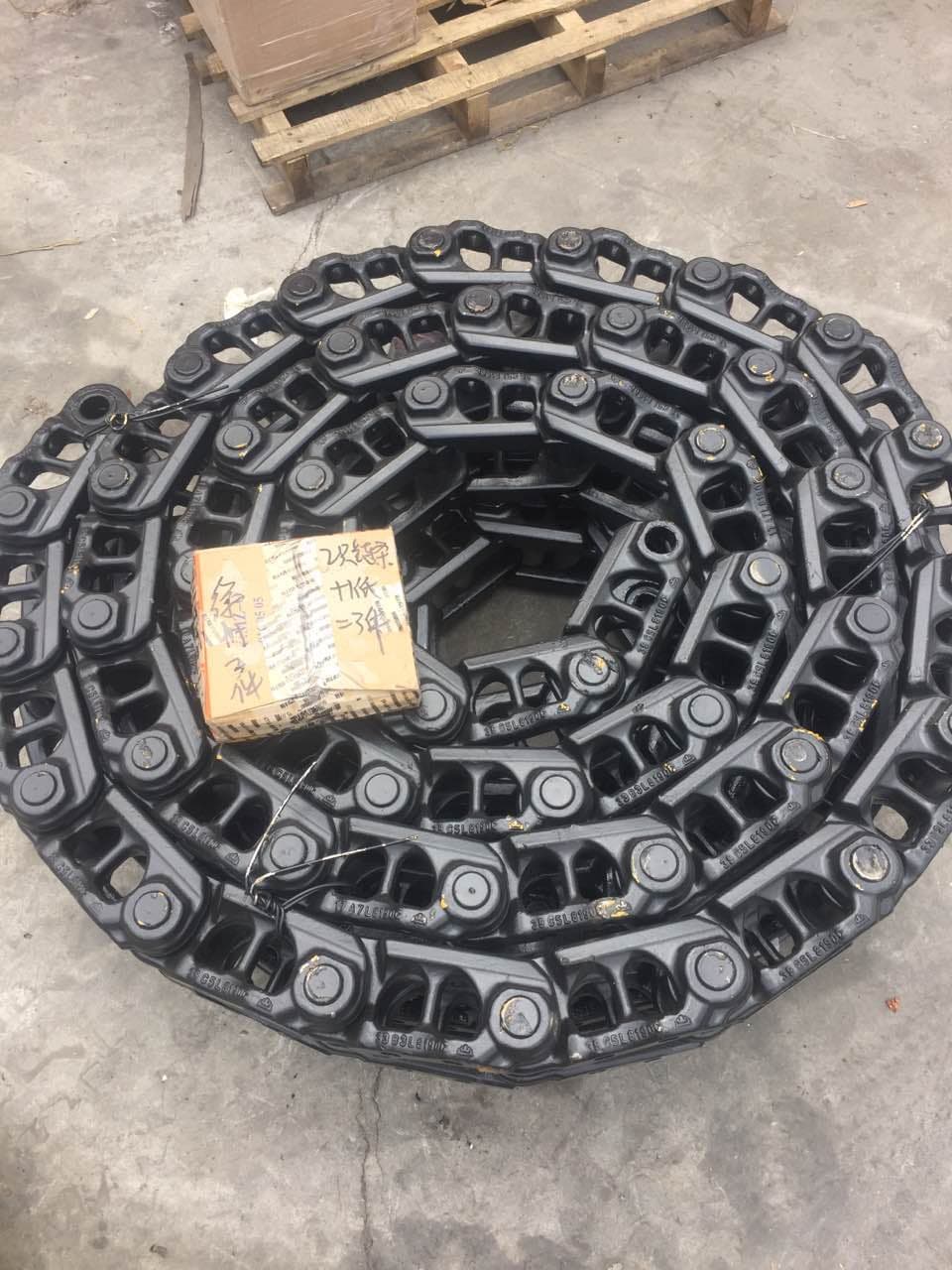
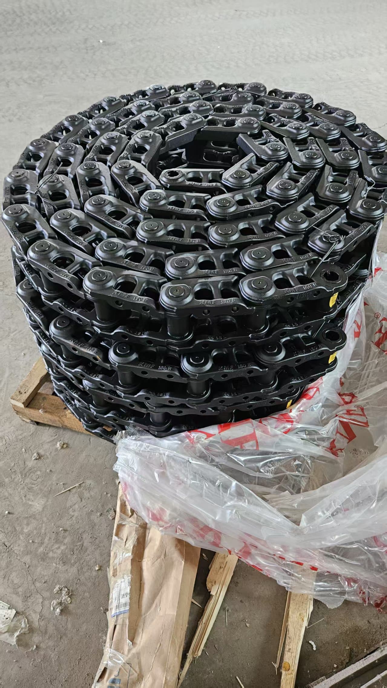
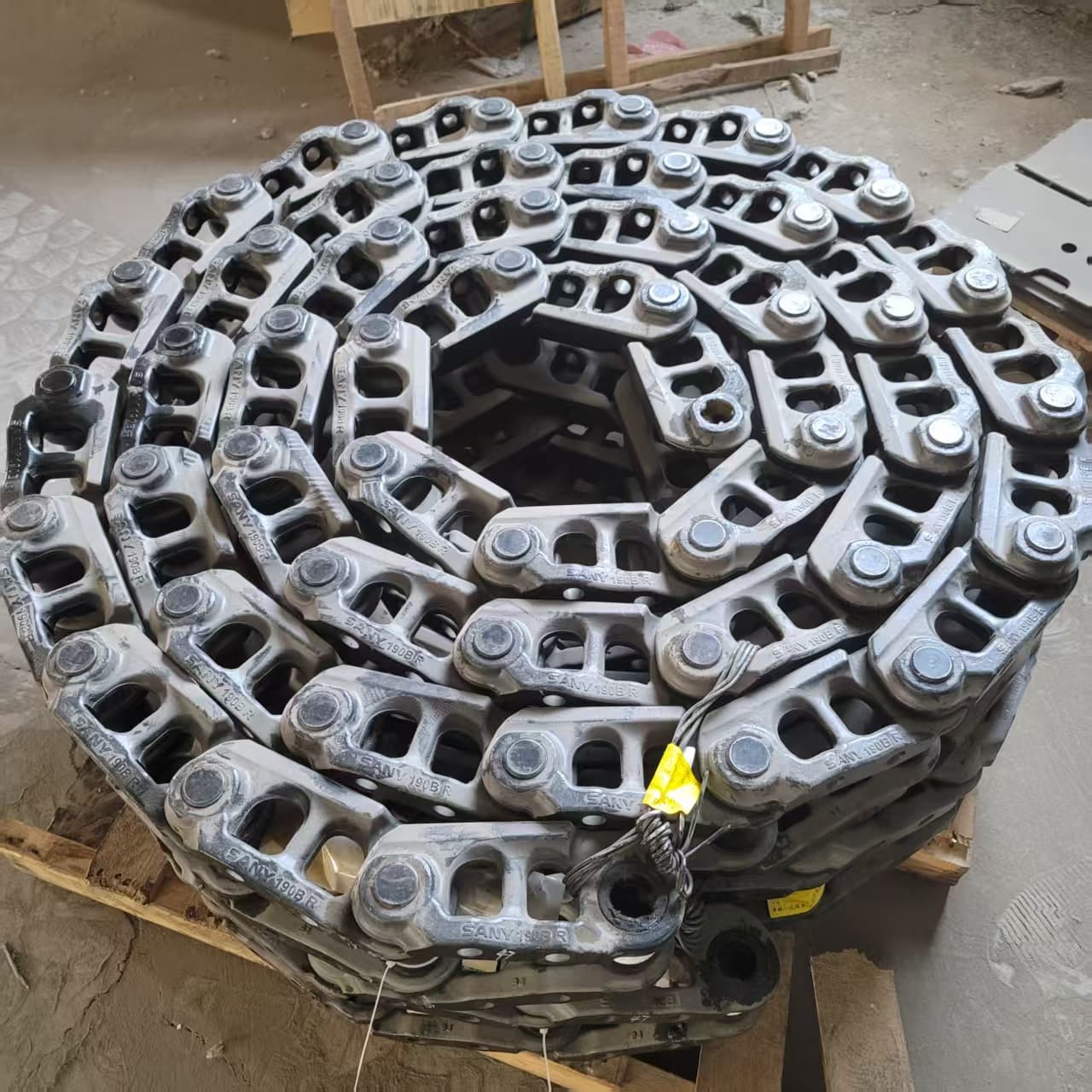
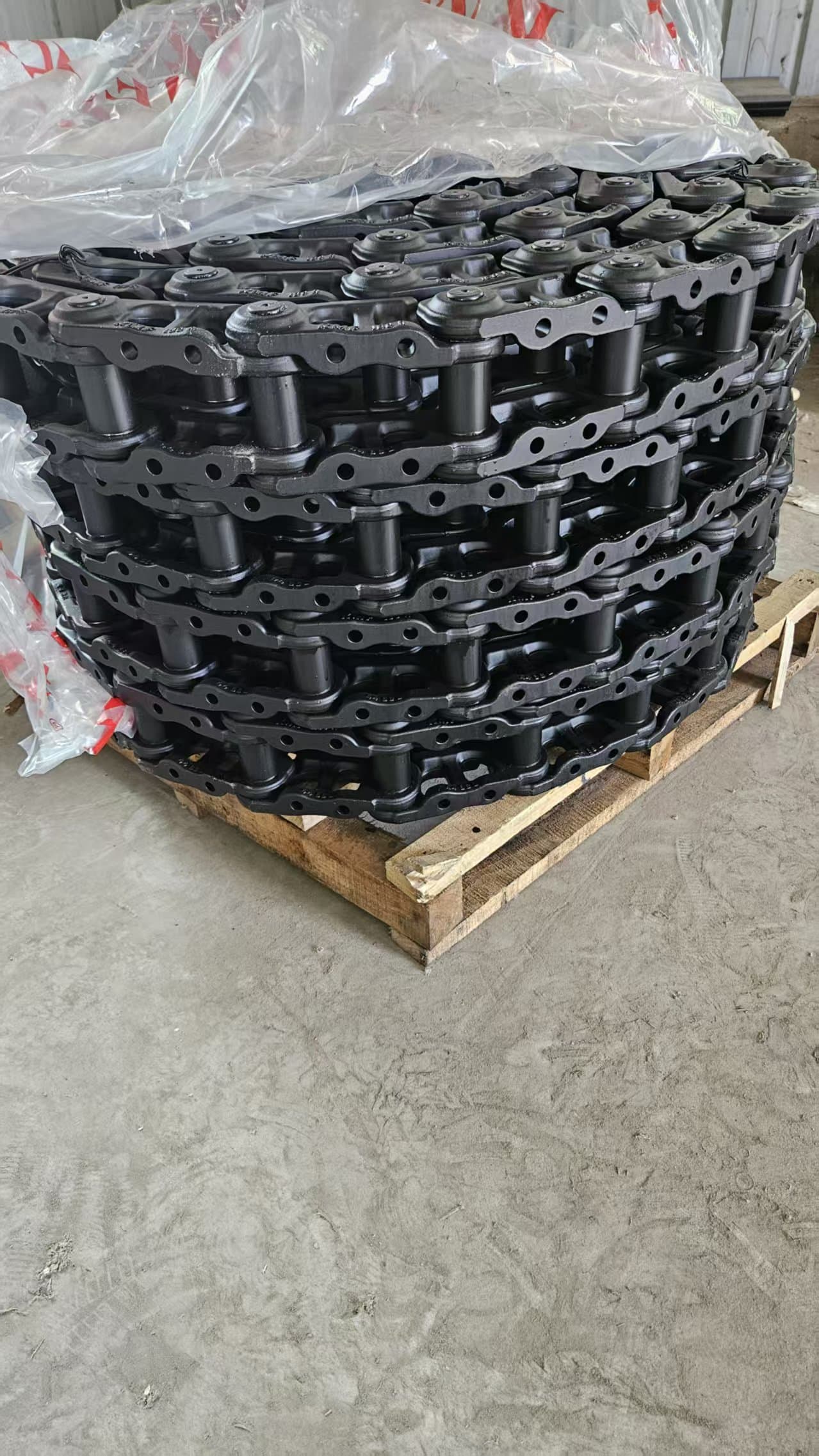
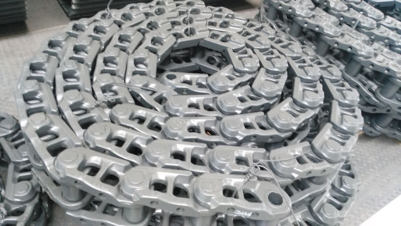
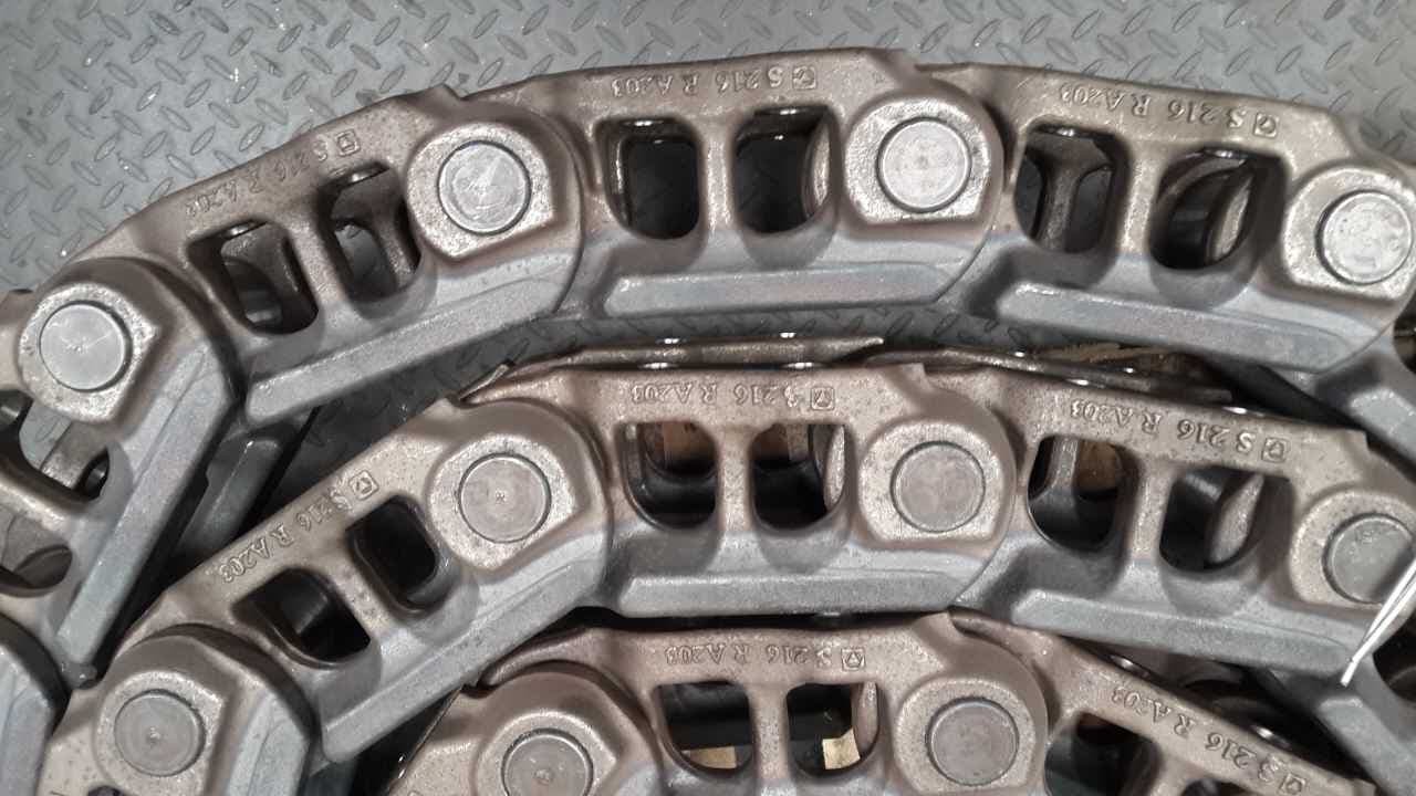
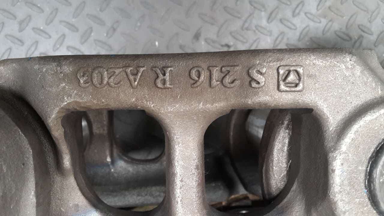
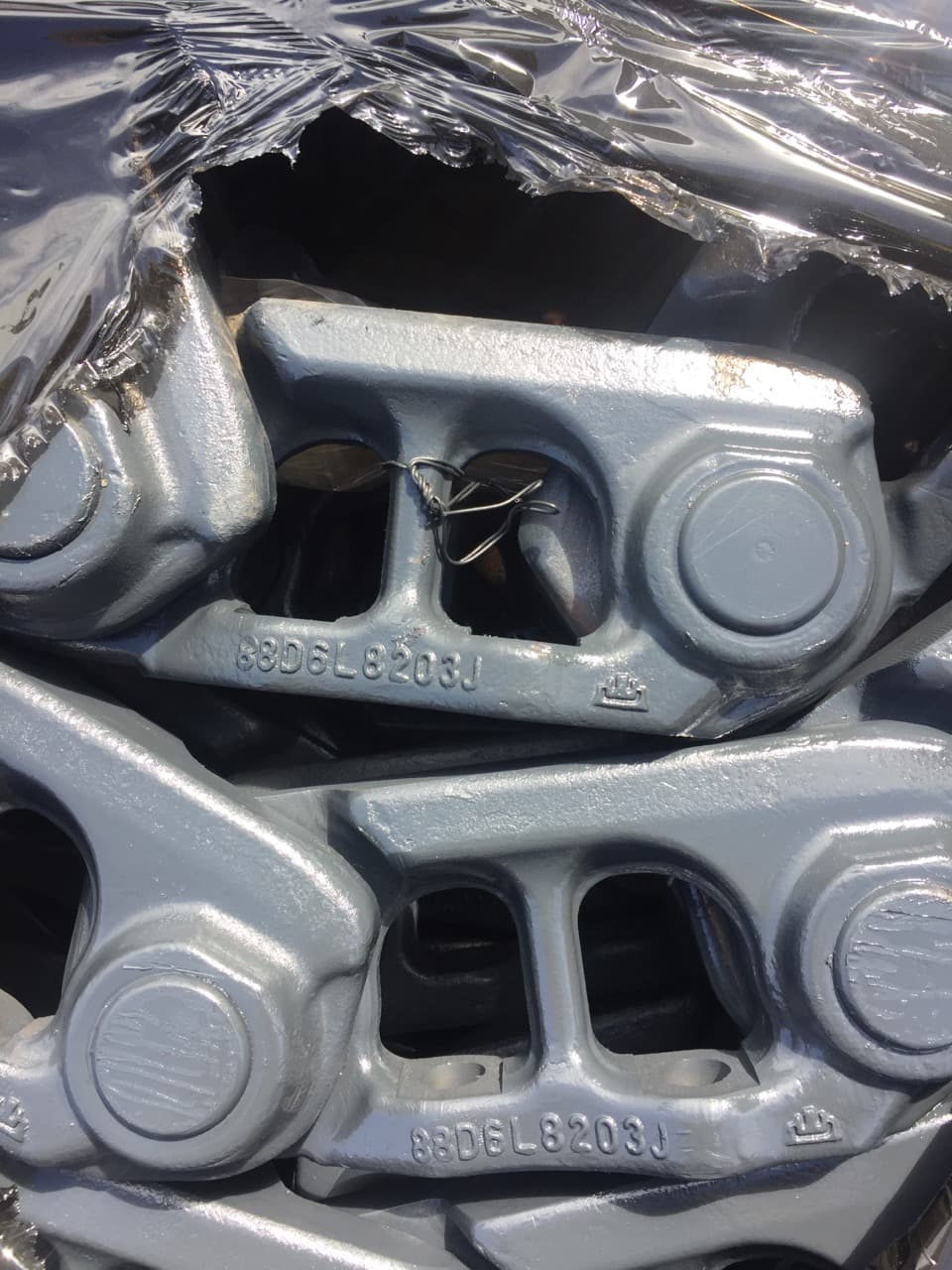
Machine Application
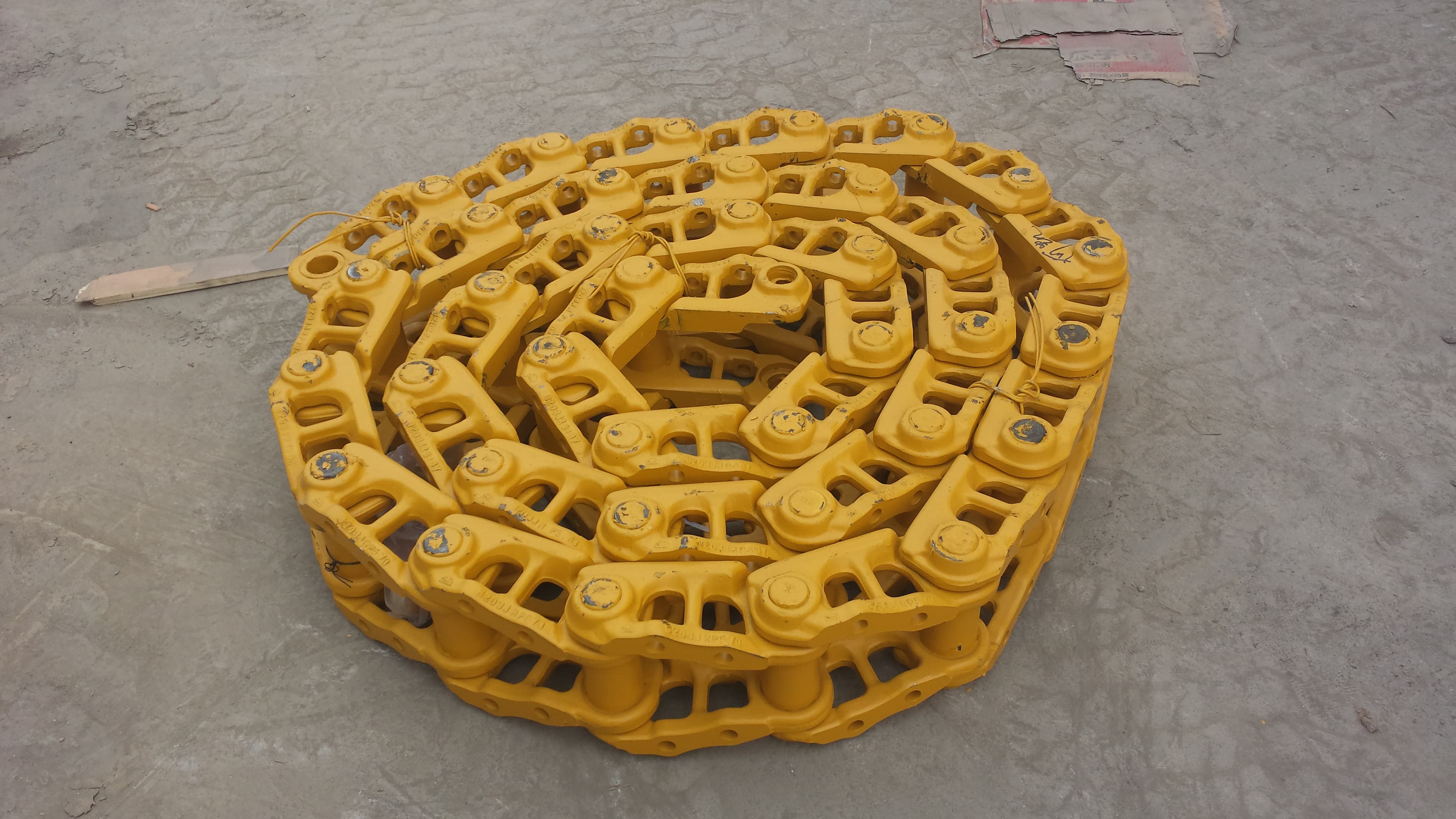
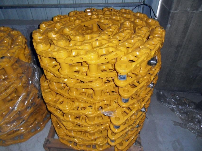
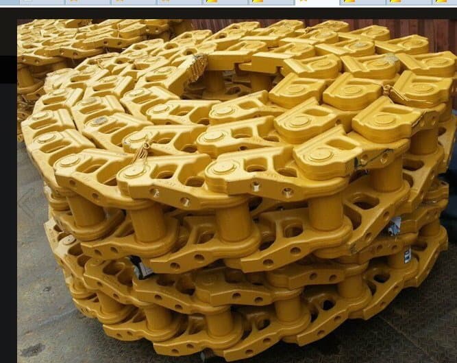
Inspection Clues
Visible or operating concerns can justify qualified inspection of the chain and connected undercarriage components. They do not establish universal wear or replacement limits.
Follow the machine-specific service guidance and use qualified technical judgment. This overview is not a repair instruction or a substitute for inspection of the actual machine.
Replacement-Part Matching
Follow this sequence for both excavators and bulldozers: model → part number → pitch → mounting pattern → duty requirement → link count → drawing. Similar-looking chains can have different interfaces, even at the same pitch.
Read the buyer guideProvide the machine make and complete model. Excavator and bulldozer chains follow the same identification sequence.
Share the chain or link-assembly part number if available, together with photos of the markings.
Measure from one pin centre to the adjacent pin centre in mm. Pitch alone does not determine the complete chain specification.
Confirm upper-row and lower-row hole centre distances, perpendicular spacing between rows and hole diameter. The shoe and chain patterns must correspond.
State the working conditions and whether a standard or mining / heavy-duty chain is required. Confirm the actual link and pin dimensions.
Confirm the number of links per chain. Separately state how many complete chains you need; chain quantity does not replace link count.
For uncertain, special or precise matching requirements, send the drawing. Include clear overall and close-up photos with the measurement points.
B2B Supply Support
Our production and international-sales teams review the confirmed chain specification, mounting interfaces, links per chain and required quantity together. The agreed configuration guides quotation, production coordination and order follow-up.
Our production and international-sales teams work together on confirmed product and order requirements.
Machine details, part references, photos, requested measurements or interface references, assembly scope, and quantity are reviewed together.
Confirmed product references, quantities, and agreed order requirements support practical quality and order follow-up.
Production-site visits can be coordinated where appropriate to the product, order stage, and agreed arrangement.
Related Track System Parts
Ground-contact components mounted to the track links.
Lower rollers supporting and guiding the loaded chain path.
Components guiding the track chain around the undercarriage.
Drive components that engage with the linked chain.
Track chain with matched shoes and fastening bolts/nuts assembled together.
Buyer Questions
A track chain is the assembled series of connected links that forms the linked running path of a tracked undercarriage. It works with the track shoes, rollers, idler, and applicable sprocket or segment drive components as part of the wider track system.
A track link is one individual link. A track chain is the assembled chain formed by multiple connected links. Buyers should state whether they need an individual link or the assembled chain rather than treating the terms as unconditional synonyms.
In parts terminology, Track Link Assembly or Link Assembly may refer to an assembled chain rather than one individual track link. Usage can vary, so the machine, photos, part reference, and requested supply scope must be confirmed before matching.
A bare track chain is the linked chain without shoes. A complete track group combines the chain, matched track shoes and fastening bolts/nuts into an assembled group; confirm both the chain and shoe configuration.
Send the machine model, part number if known, pitch, shoe mounting-hole pattern, standard or heavy-duty requirement, and links per chain. Link count is required for quotation. Include the number of chains, photos and a drawing for uncertain, special or precise requirements.
Request for Quotation
Include the machine model, part number, pitch, mounting-hole pattern and standard / heavy-duty requirement. Link count per chain is required for quotation; state the number of chains separately. Add these details, photos and any drawing to your inquiry so FY can confirm the specification.