FY MachineryUndercarriage Parts

Undercarriage Product Group

Track Adjusters & Recoil Springs

FY Machinery supplies complete track adjuster assemblies and individual cylinders, recoil springs and support components for excavator and bulldozer undercarriages. An excavator assembly typically combines the adjuster cylinder, recoil spring and U-shaped mounting / support structure. Confirm the machine model, part number, mounting dimensions and overall length before quotation.

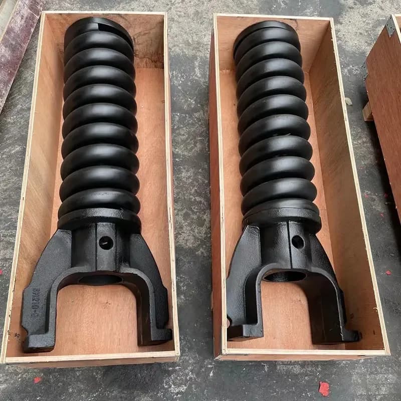
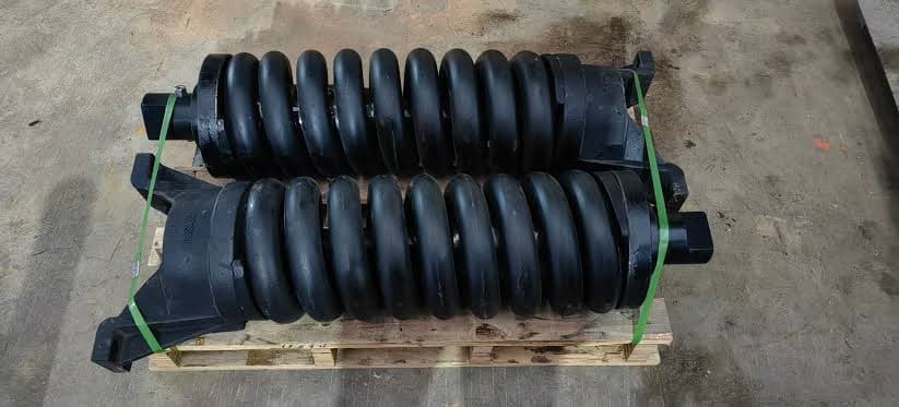
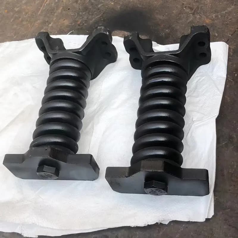
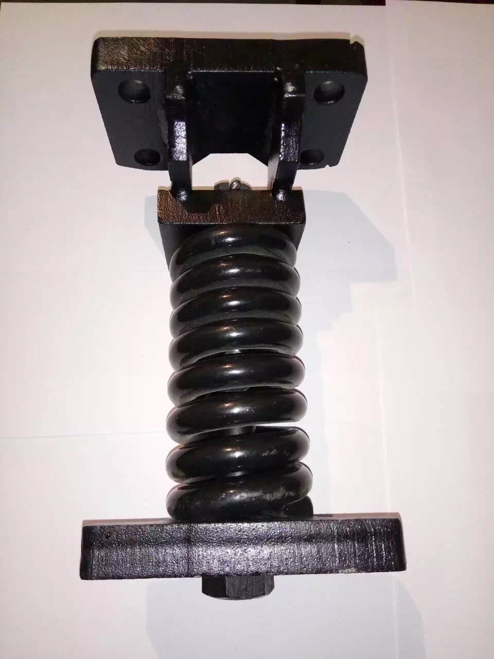
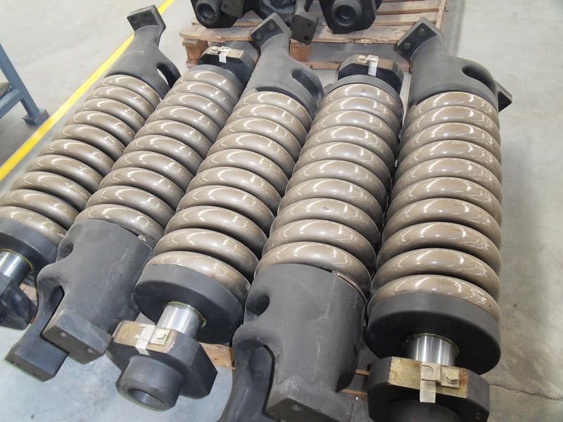
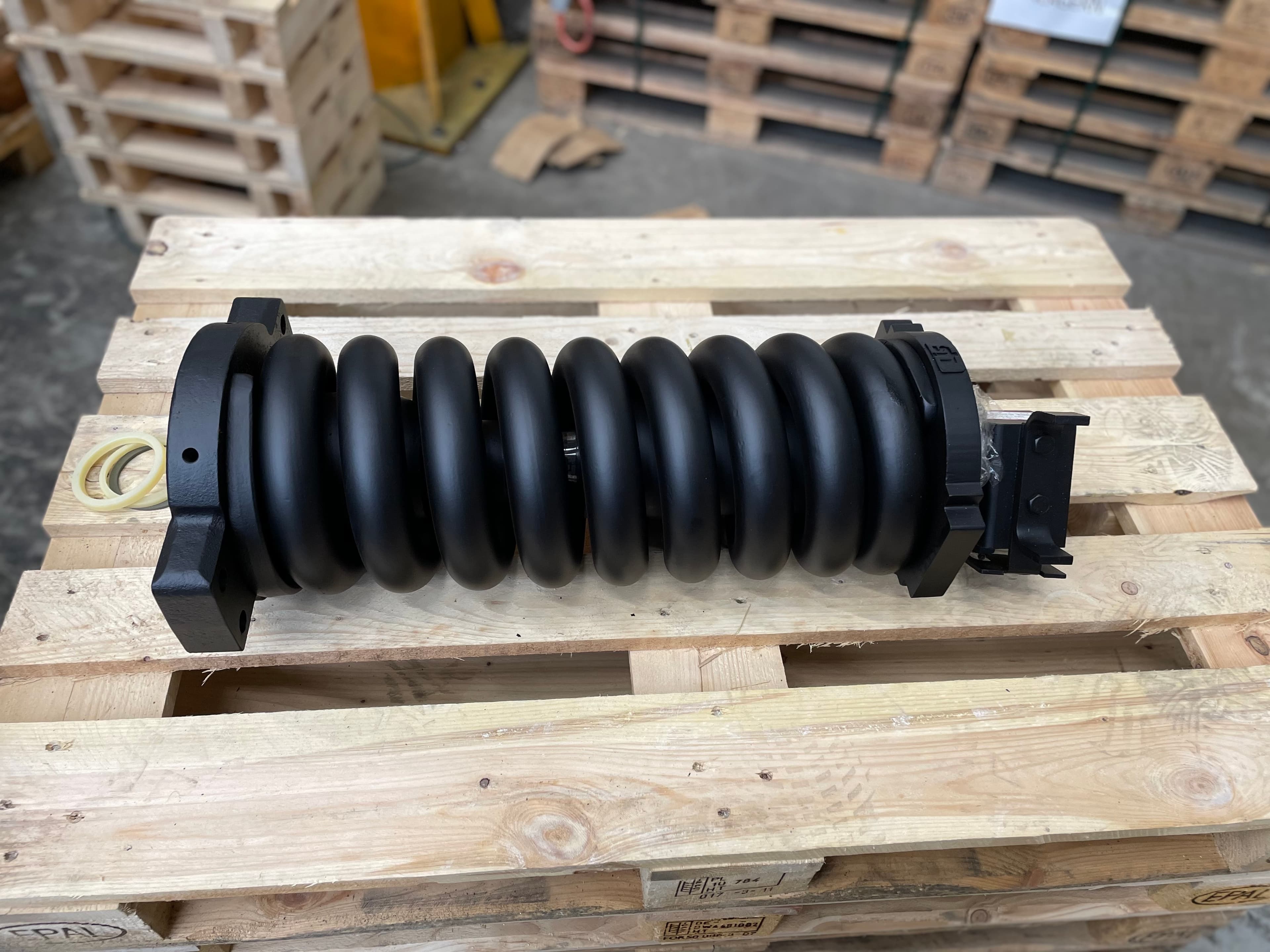
Track adjuster and recoil spring assemblies arranged for product identification
Product GroupTrack System

Track Adjusters & Recoil Springs

Complete Assemblies & ComponentsMounting Centres & Overall Length

Product structure & supply scope

One complete assembly. Three main elements.

An excavator complete track adjuster assembly typically combines a track adjuster cylinder + recoil spring + U-shaped mounting / support structure. Customers commonly request the assembled unit. FY can also supply individual cylinders, springs and support components, with the required scope confirmed for the specific machine.

FY complete adjuster concept: support structure, cylinder and recoil spring1 · Cylinder2 · Spring3 · U-shaped / support structure
Assembly concept, not to scale. Actual support shape and interfaces vary by configuration.

Complete Track Adjuster Assembly

Specify the assembled cylinder, spring and support arrangement, together with mounting measurements and overall length.

Individual components

Identify the cylinder, recoil spring or support component you need. Include photos and the part number so a component request is not confused with a complete unit.

Request an assembly or component →

Machine Applications

System role and related undercarriage context

The track-adjustment and recoil system works with the front idler to support the undercarriage's tensioning function and accommodate recoil movement as operating loads change. Component layout and assembly scope vary by machine, so this overview does not provide model-specific tension settings or service procedures.

Excavator Application

Excavator Track Adjusters

An excavator track adjuster works within the machine's front-idler and track-tensioning arrangement. Replacement matching depends on the actual machine and on whether the request covers an individual component or a wider assembly.

View Excavator Undercarriage Parts

Bulldozer Application

Bulldozer Track Tensioning Components

Bulldozer track adjuster and recoil-component requests are reviewed in the context of the machine's front-idler and tensioning arrangement. No component form or assembly scope should be assumed across different machines.

View Bulldozer Undercarriage Parts

Related Component

Idlers

The adjuster or tensioner arrangement works in relation to the front idler. Idler position and interface details can therefore provide useful context when a replacement part is being identified.

View Idlers

Related Component

Track Chains

Track-tension behavior is observed within the wider track system. Track chain and undercarriage configuration details can help clarify the application during product matching.

View Track Chains

FY technical guide · Type A–F

Recognise the configuration before comparing dimensions

Type E and F are commonly requested complete-assembly configurations. Type A–D cover cylinder, component and other reference layouts. These letters identify the supplied reference set; confirm the actual supply scope and mounting configuration for your machine.

Type E

Common complete assembly
FY Type E reference configuration, axial and mounting-end viewsAMGAxial reference viewEFMounting-end reference view
Commonly requested complete-assembly configuration, shown with an angled support layout.
Compare Type E references →

Type F

Common complete assembly
FY Type F reference configuration, axial and mounting-end viewsAGAxial reference viewEFMounting-end reference view
Commonly encountered complete-assembly configuration, shown with a U-shaped support layout.
Compare Type F references →

Type A

FY Type A reference configuration, axial and mounting-end viewsABCAxial reference viewFEMounting-end reference view
Flanged cylinder reference with a rectangular mounting-end layout.
Compare Type A references →

Type B

FY Type B reference configuration, axial and mounting-end viewsABCAxial reference viewEFMounting-end reference view
Cylinder reference with a circular flange layout.
Compare Type B references →

Type C

FY Type C reference configuration, axial and mounting-end viewsAAxial reference viewEFMounting-end reference view
Spring / adjuster reference configuration. Confirm the exact component or assembly scope.
Compare Type C references →

Type D

FY Type D reference configuration, axial and mounting-end viewsAMAxial reference viewFEMounting-end reference view
Spring / adjuster reference configuration with separate A and M axial spans.
Compare Type D references →

FY original schematics · Not to scale · Buyer reference only. A is the axial span shown for Types A–C/E/F; Type D uses M for the overall reference span and A for the shorter spring span. Other letters retain their raw values in the specifications. Exact letter-to-feature mappings, endpoints and tolerances must be checked on the product drawing. P/K labels without table values are omitted.

How to measure

Mounting-hole centres and overall length come first

Start with the machine model and part number. Identify a welded, single-hole-per-side or double-hole-per-side mounting arrangement. Measure the bolt-hole centre distances on the bottom / support mounting interface, following the same centre-to-centre logic as the idler. Also record the overall length and mark the endpoints.

Welded support

Welded support: supply an interface drawingMark the welded interfaces
Provide a marked drawing of the support and attachment interfaces.

Single hole per side

Measure between left and right hole centresCentre → centreUse hole centres, not edges
Record the distance across the two mounting-hole centres.

Double holes per side

Measure across the sides and between both hole rowsCentre → centre2Use hole centres, not edges
Record across-side and same-side hole centre distances; identify the orientation.

Send a drawing for accurate confirmation

Include measured mounting dimensions and overall length with units, photos, the machine model and any part number. Special / custom specifications require both a drawing and the pressure requirement. State the required pressure and its units in your inquiry; the reference tonnage is not a pressure rating.

Mounting examples explain the measuring method; they do not assign an installation form to every Type or code. Compare the idler mounting guide →

Selected technical references

15 configurations across Type A–F

Representative technical dimensions only, covering reference machine tonnages from 1.5T to 30T. Tonnage helps compare the reference range; it does not confirm fitment, pressure capability or the complete FY supply range. Type E/F are emphasised because these complete-assembly layouts are commonly requested.

Read the original values: dimensions use mm; letter meanings vary by Type. / = not provided. 0 remains the supplied numeric zero. Diameter and thread strings such as Ø80, 2-M12 and M12 are retained. Expand a reference for all A–H, M and T values. Reference length follows the drawn A span, or M for Type D; mark the actual overall-length endpoints on your drawing.

Type A · Flanged cylinder references

View configurations ↑

Tap a card for all 10 raw reference fields.

CY03534Type A · 3.5TReference length: A · 177 mm
A
177
B
15
C
Ø80
D
83
E
136
F
60
G
/
H
Ø12
M
/
T
/

Mounting form, exact measurement points and final configuration require confirmation against the drawing.

CY05501Type A · 6.0TReference length: A · 215 mm
A
215
B
45
C
Ø80
D
79
E
179
F
50
G
/
H
Ø14
M
/
T
/

Mounting form, exact measurement points and final configuration require confirmation against the drawing.

CY20050Type A · 20.0TReference length: A · 192 mm
A
192
B
30
C
Ø121
D
Ø140
E
120
F
0
G
/
H
M12
M
/
T
/

Mounting form, exact measurement points and final configuration require confirmation against the drawing.

Type B · Circular-flange cylinder references

View configurations ↑

Tap a card for all 10 raw reference fields.

CY07002Type B · 7.0TReference length: A · 194 mm
A
194
B
29
C
Ø80
D
/
E
Ø130
F
Ø110
G
/
H
2-M12
M
/
T
/

Mounting form, exact measurement points and final configuration require confirmation against the drawing.

CY08026Type B · 8.0TReference length: A · 189 mm
A
189
B
30
C
Ø102
D
/
E
Ø140
F
Ø120
G
/
H
M12
M
/
T
/

Mounting form, exact measurement points and final configuration require confirmation against the drawing.

Type C · Spring / adjuster reference configurations

View configurations ↑

Tap a card for all 10 raw reference fields.

RE01301Type C · 1.5TReference length: A · 224 mm
A
224
B
/
C
/
D
Ø79
E
100
F
46
G
Ø11
H
/
M
/
T
/

G=Ø11 and H=/ remain as supplied; do not reassign the value to another letter. Mounting form, exact measurement points and final configuration require confirmation against the drawing.

RE02526Type C · 2.5TReference length: A · 237 mm
A
237
B
/
C
/
D
Ø84
E
106
F
50
G
/
H
Ø11
M
/
T
/

Mounting form, exact measurement points and final configuration require confirmation against the drawing.

RE05526Type C · 5.0TReference length: A · 325 mm
A
325
B
/
C
/
D
Ø106
E
156
F
56
G
/
H
Ø13.5
M
/
T
/

Mounting form, exact measurement points and final configuration require confirmation against the drawing.

Type D · Spring / adjuster reference configurations

View configurations ↑

Tap a card for all 10 raw reference fields.

RE03534Type D · 3.5TReference length: M · 260 mm
A
236
B
/
C
/
D
Ø78
E
114
F
110
G
/
H
Ø40
M
260
T
/

M is the overall reference span; A is the shorter spring span. Mounting form, exact measurement points and final configuration require confirmation against the drawing.

RE05501Type D · 6.0TReference length: M · 370 mm
A
330
B
/
C
/
D
Ø100
E
107
F
214
G
/
H
Ø44
M
370
T
/

M is the overall reference span; A is the shorter spring span. Mounting form, exact measurement points and final configuration require confirmation against the drawing.

Type E · Common complete-assembly references

View configurations ↑

Tap a card for all 10 raw reference fields.

RE08501Type E · 8.0TReference length: A · 520 mm
A
520
B
Ø120
C
135
D
Ø135
E
205
F
56
G
54
H
M12
M
/
T
10

Mounting form, exact measurement points and final configuration require confirmation against the drawing.

Type F · Common complete-assembly references

View configurations ↑

Tap a card for all 10 raw reference fields.

RE06546Type F · 6.5TReference length: A · 355 mm
A
355
B
Ø110
C
112
D
Ø114
E
160
F
35
G
120
H
Ø11.5
M
55
T
15

Mounting form, exact measurement points and final configuration require confirmation against the drawing.

RE13501Type F · 15.0TReference length: A · 790 mm
A
790
B
Ø65
C
155
D
Ø190
E
210
F
0
G
120
H
Ø18
M
70
T
0

Mounting form, exact measurement points and final configuration require confirmation against the drawing.

RE22501Type F · 20.0TReference length: A · 713 mm
A
713
B
Ø120
C
182
D
Ø242
E
280
F
66
G
116
H
Ø17.5
M
100
T
19.5

Mounting form, exact measurement points and final configuration require confirmation against the drawing.

RE35001Type F · 30.0TReference length: A · 1130 mm
A
1130
B
Ø120
C
210
D
Ø262
E
360
F
60
G
140
H
Ø22
M
110
T
0

Mounting form, exact measurement points and final configuration require confirmation against the drawing.

Confirm the specification in your inquiry

Choose complete assembly or individual component. In the inquiry message, include the mounting form, bolt-hole centre distances, overall length with units, a drawing reference and the required quantity. Use the existing form for machine model and part number. Special specifications additionally require a drawing and pressure requirement with units. Final configuration must be confirmed by model, part number, drawing and measured mounting dimensions.

Send Track Adjuster / Recoil Spring RFQ →

Product Media

Track Adjusters & Recoil Springs Product Images

Track Adjusters & Recoil Springs

Main Product View

Track adjuster and recoil spring assembly product view

Product Gallery

Track adjuster and recoil spring assemblies product view
Track adjuster and recoil spring assembly pair view
Track adjuster and recoil spring assembly view
Track adjuster and recoil spring assembly vertical view

Product Details

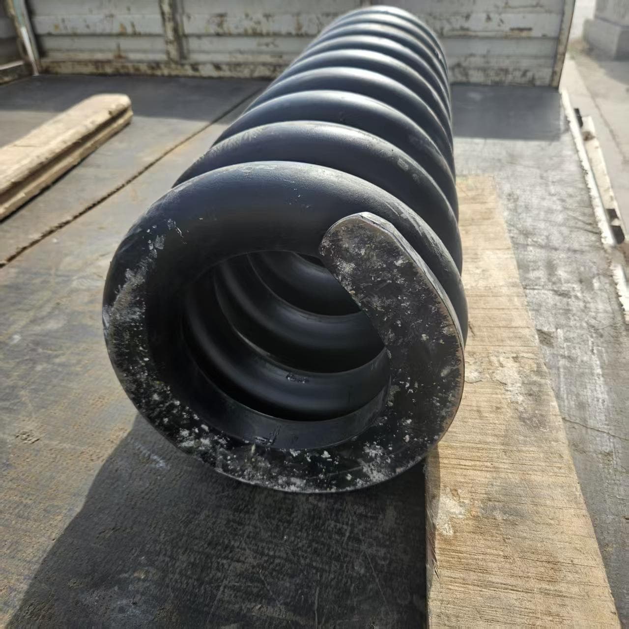
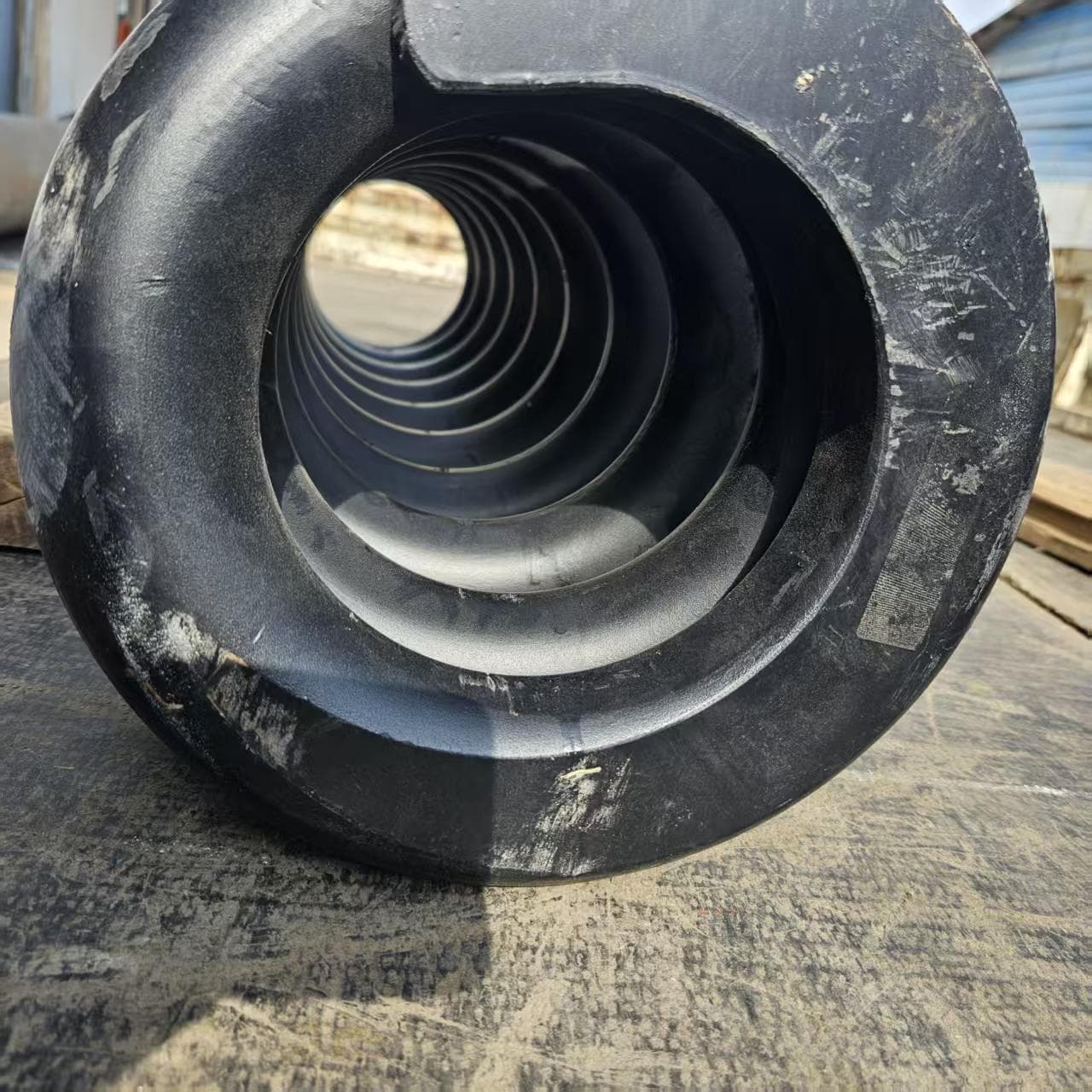
Track adjuster and recoil spring end detail
Track adjuster and recoil spring housing detail
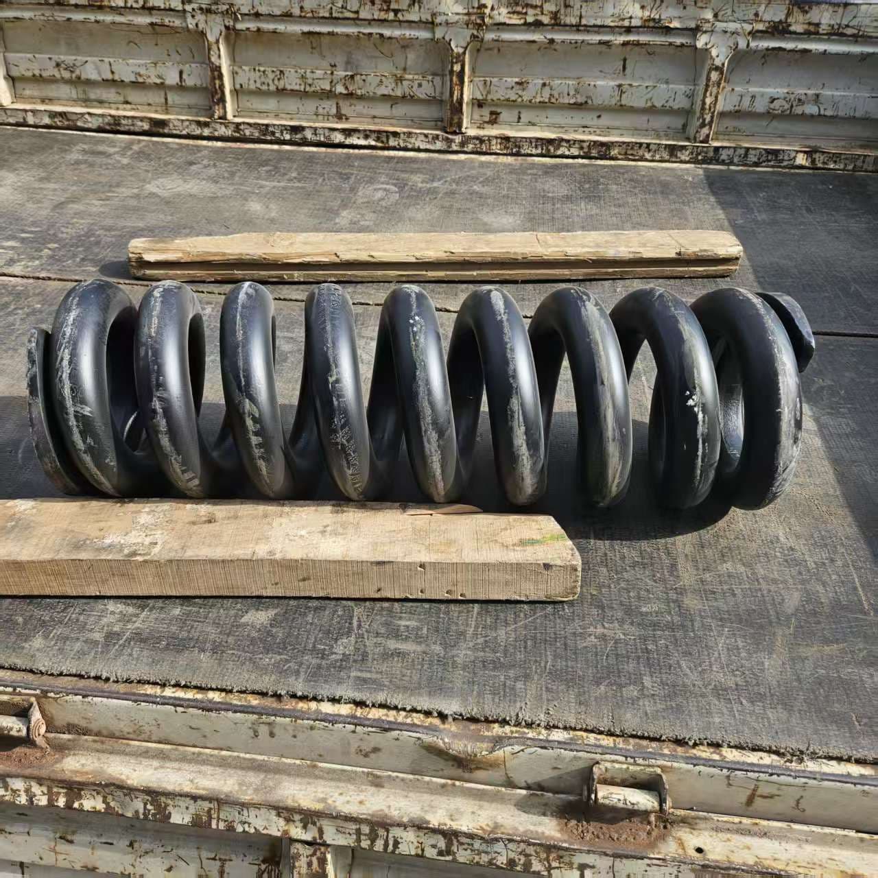
Recoil spring component detail

Product Configuration

Track adjuster, track tensioner, and recoil spring terms

Buyer and supplier terminology is not always used at the same level of assembly. The machine, existing part, interfaces, and requested supply scope must be checked before treating a name as a complete product definition.

01

Buyer Terminology

Track Adjuster and Track Tensioner

In parts terminology, Track Adjuster and Track Tensioner may refer to the tensioning function or to an assembly that performs it. The exact meaning should be confirmed for the specific request.

02

Component Scope

Recoil Spring

Recoil Spring refers specifically to the spring or recoil component. It should not be treated as an unconditional synonym for a complete track adjuster or track tensioner assembly.

03

Assembly Review

Assembly Names Need Confirmation

Track Adjuster Assembly, Track Tensioner Assembly, Recoil Spring Assembly, and Track Adjuster Spring Assembly may describe different scopes depending on the machine and supplier terminology.

04

Inspection Context

High-Level Inspection Clues

Leakage, visible damage, broken or displaced components, abnormal track-tension behavior, or unusual movement are reasons for qualified inspection. They are not universal replacement limits or repair instructions.

Product Identification

Information needed to match track adjusters and recoil springs

Similar-looking parts may have different interfaces or supply scopes. The following identification details help FY Machinery compare the requirement and prepare a clearer B2B quotation without assuming compatibility from appearance alone.

Read the buyer guide
01

Machine make and model

Provide the manufacturer name and complete model designation shown in the machine records or on the identification plate.

02

Available part number

Share any reliable number from the existing adjuster or recoil spring, parts documentation, purchase record, or other available reference.

03

Overall and close-up photos

Send clear overall views plus close-ups of connection areas, interfaces, markings, visible damage, and the relationship with the front idler where practical.

04

Requested dimensions and interfaces

Identify welded, single-hole-per-side or double-hole-per-side mounting. Measure the bolt-hole centre distances at the bottom / support interface and the overall length, with units and clearly marked measurement points.

05

Required assembly scope

Choose a complete assembled track adjuster or an individual cylinder, recoil spring or support component. Include a photo showing the exact scope required.

06

Required quantity

State the quantity required for the quotation and indicate whether the request covers individual components or matched assemblies.

07

Drawing and special requirements

A drawing is preferred for accurate confirmation. Special / custom specifications require a drawing plus the pressure requirement with units; tonnage does not replace a pressure requirement.

Order Review & Packing

Matching, production, and order follow-up

Our production and international-sales teams work together on confirmed product and order requirements. Matching begins with the machine, requested assembly or component, mounting dimensions and drawing references.

Product matching

Machine information, part references, photos, requested dimensions or interface references, required scope, and quantity are reviewed together before a replacement option is proposed.

Direct production coordination

Our production and sales teams coordinate after the part, assembly scope and order requirements have been clarified.

Quality and order follow-up

Confirmed product references, quantities, and agreed order requirements support practical quality and order follow-up during coordination.

Production-site visit support

Where appropriate, FY Machinery can help coordinate a production-site visit after the inquiry scope and visit arrangements are confirmed.

Buyer Questions

Track adjuster and recoil spring FAQ

Can FY supply both assembled units and separate components?

Yes. FY can supply a complete assembled track adjuster or individual cylinders, recoil springs and support components. An excavator complete assembly typically combines a track adjuster cylinder, recoil spring and U-shaped mounting / support structure. Confirm the exact scope for the machine before quotation.

Are Type E and F the only available configurations?

No. Type E and F are commonly requested complete-assembly reference configurations. Type A–D illustrate cylinders, components and other layouts. The selected dimensions are representative references, and final configuration requires the machine model, part number, drawing and mounting measurements.

What is required for a special track adjuster specification?

Provide a drawing and the pressure requirement with units, together with the machine details, requested scope, mounting dimensions and overall length. The reference tonnage does not identify a pressure rating.

What is a track adjuster?

A track adjuster is part of the undercarriage's track-adjustment system. It works with the relevant front-idler arrangement to support the tensioning function, but its exact component and assembly scope varies by machine.

Is a track adjuster the same as a track tensioner?

The terms are sometimes used for the same tensioning function or assembly in parts inquiries, but their intended scope is not universal. Confirm the machine, existing part, interfaces, and requested assembly before matching.

Is a recoil spring the same as a complete track adjuster?

No. A recoil spring is the spring or recoil component and should not automatically be treated as the complete adjuster. A Recoil Spring Assembly may also describe a different supply scope depending on the machine and supplier terminology.

What information helps match a replacement track adjuster or recoil spring?

Provide machine make and model, part number if known, complete assembly or component scope, photos, quantity, mounting form, bolt-hole centre distances and overall length with units. A drawing is preferred; special specifications require a drawing and pressure requirement.

When should the track-adjustment system be inspected?

Arrange a qualified inspection when leakage, visible damage, broken or displaced components, abnormal track-tension behavior, or unusual movement is observed. These clues are not universal replacement limits, maintenance intervals, or repair instructions.
Send an Inquiry

Request a track adjuster or recoil spring quotation

Choose complete assembly or individual component. Enter the machine model and part number in the inquiry form; include mounting form, bolt-hole centre distances, overall length with units, drawing reference and quantity in the message. For special specifications, also provide the drawing and pressure requirement with units.